Industrial robot

a robot and industrial technology, applied in the field of industrial robots, can solve the problems of complex mechanism for grasping and releasing semiconductor wafers, industrial robots placed in vacuum chambers, and inability to grasp semiconductor wafers by vacuum chucking, etc., to achieve simple construction and reduce physical impact

Inactive Publication Date: 2011-10-25
SANKYO SEIKI MFG CO LTD
View PDF4 Cites 3 Cited by
  • Summary
  • Abstract
  • Description
  • Claims
  • Application Information

AI Technical Summary

Benefits of technology

[0011]At least an embodiment of the present invention provides an industrial robot that can reduce a physical impact to be made upon a transfer object when the transfer object is grasped by mechanical construction.
[0012]At least an embodiment of the present invention provides an industrial robot that can grasp and release a transfer object by using simple construction.

Problems solved by technology

Though an industrial robot operating in the atmosphere can commonly apply a method of grasping a semiconductor wafer by vacuum chucking, an industrial robot placed in a vacuum chamber cannot grasp a semiconductor wafer by vacuum chucking.
However, the clamping mechanism for semiconductor wafers proposed by Patent Document 1 is not provided with sufficient consideration for clamping such a thin-profiled wafer.
Therefore, the clamping mechanism for semiconductor wafers described in Patent Document 1 is in danger of making a physical impact against a semiconductor wafer when grasping the semiconductor wafer so as to eventually cause damage to the semiconductor wafer.
Consequently, the mechanism for grasping and releasing the semiconductor wafer becomes complicated.

Method used


Image

  • Industrial robot
  • Industrial robot
  • Industrial robot

Examples


first embodiment

(Schematic View of Industrial Robot)

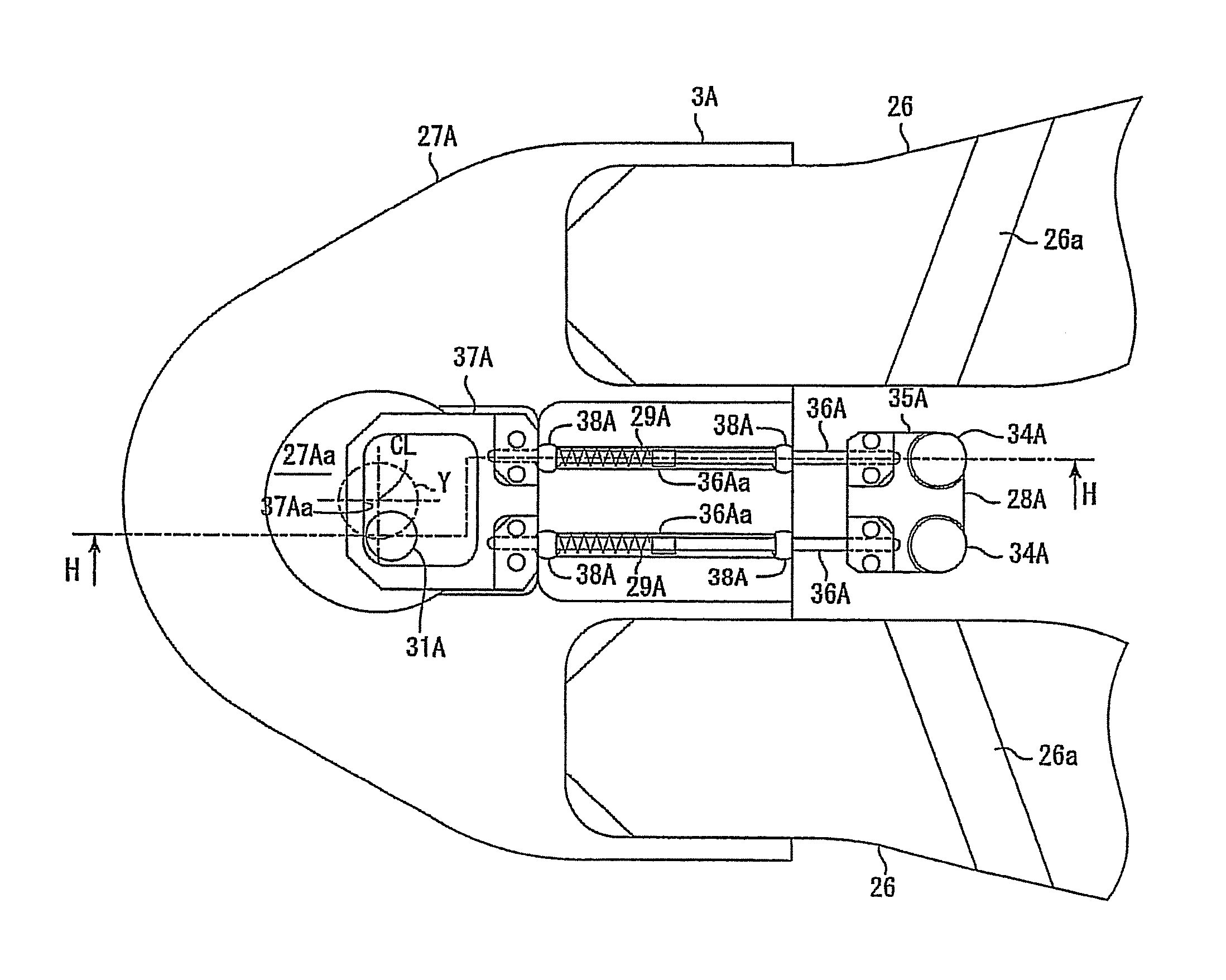
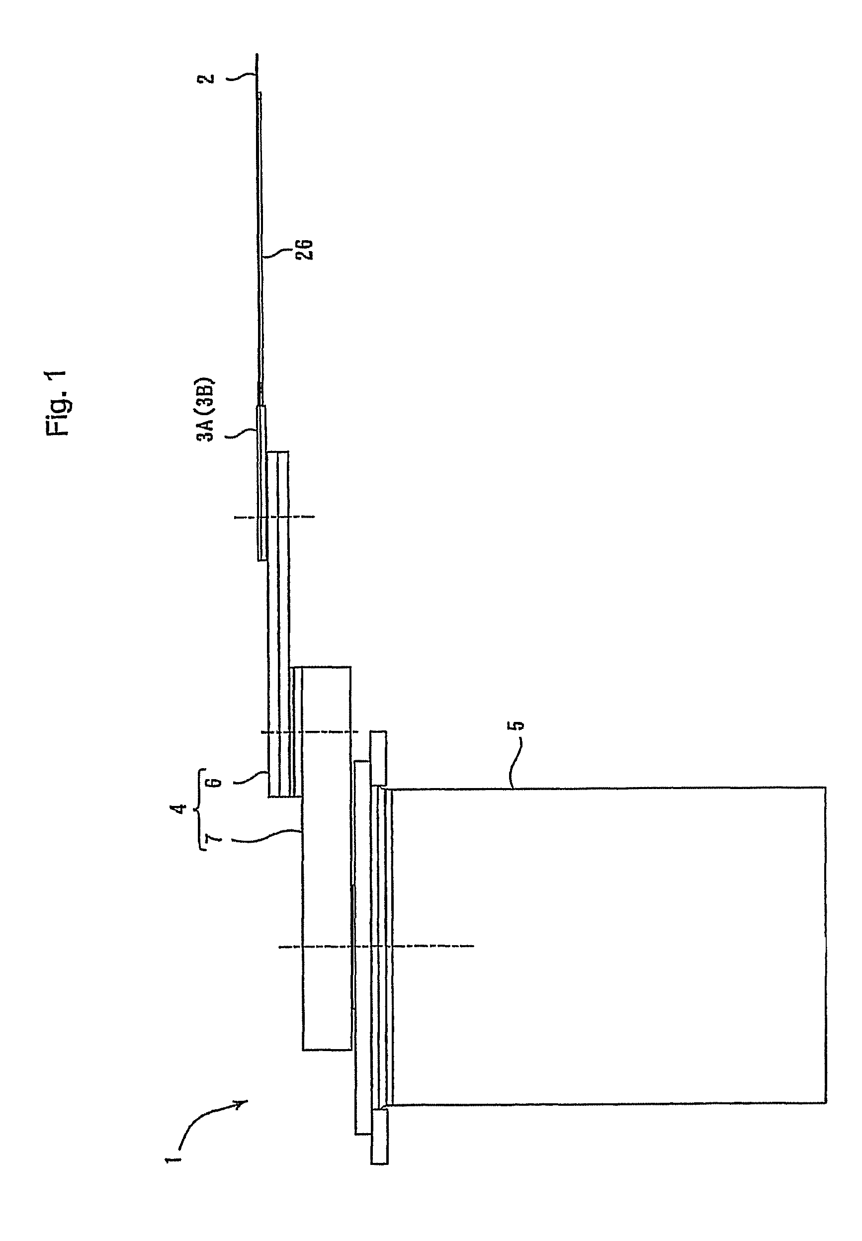
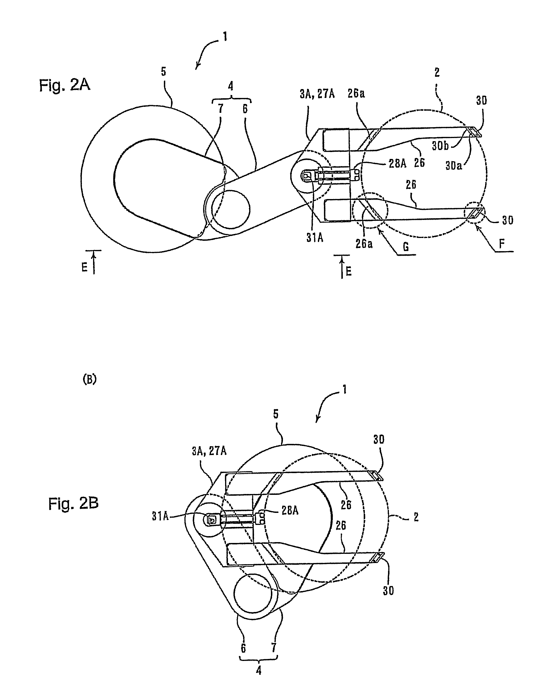
[0058]FIG. 1 is a side view showing an industrial robot 1 according to at least an embodiment of the present invention. FIG. 2 illustrates plan views of the industrial robot 1 shown in FIG. 1, wherein FIG. 2A illustrates a posture in which a multi-joint arm section 4 is expanded and FIG. 2B illustrates another posture in which the multi-joint arm section 4 is folded. FIG. 3 is a plan view showing a schematic view of a semiconductor manufacturing system 9 in which the industrial robot 1 shown in FIG. 1 is built. FIG. 4 is a schematic sectional view for describing a power transmission mechanism inside the multi-joint arm section 4 and a robot hand 3A, both of which are shown in FIG. 1. FIGS. 5A-5D a relationship between the expanding / folding condition of the multi-joint arm section 4, shown in FIG. 1, and the orientation of the robot hand 3A. Meanwhile, FIG. 4 is a schematic sectional view of the multi-joint arm section 4 and others when these parts...

second embodiment

[0130]At least a second embodiment of the present invention is described below with reference to the accompanying drawings. Incidentally, the same symbols as those of the first embodiment described before are used for functions corresponding to the like functions of the second embodiment.

(Schematic View of Industrial Robot)

[0131]FIG. 1 is a side view showing an industrial robot 1 according to at least an embodiment of the present invention. FIGS. 17A-17B are plan views of the industrial robot 1 shown in FIG. 1, wherein FIG. 17A illustrates a posture in which a multi-joint arm section 4 is expanded and FIG. 17B illustrates another posture in which the multi-joint arm section 4 is folded. FIG. 3 is a plan view showing a schematic view of a semiconductor manufacturing system 9 in which the industrial robot 1 shown in FIG. 1 is built. FIG. 4 is a schematic sectional view for describing a power transmission mechanism inside the multi-joint arm section 4 and a robot hand 3B, both of which...


PUM


Abstract

An industrial robot may include a robot hand structured to mount a transfer object, a multi-joint arm section having at least two arms including a robot hand supporting arm structured to support the robot hand to be rotatable; and a main section structured to support the multi-joint arm section to be rotatable. The robot hand may include a grasping part structured to contact and grasp the transfer object and a biasing member structured to bias the grasping part in a direction for grasping the transfer object. The robot hand supporting arm may include an eccentric member fixed to the robot hand supporting arm at a position being eccentric from a turning center of the robot hand in relation to the supporting arm.

Description

CROSS REFERENCE TO RELATED APPLICATION[0001]The present invention claims priority under 35 U.S.C. §119 to Japanese Application No. 2007-149267 filed Jun. 5, 2007 and Japanese Application No. 2007-164948 filed Jun. 22, 2007, both of which are incorporated herein by reference.FIELD OF THE INVENTION[0002]The present invention relates to an industrial robot that transfers a specific transfer object.BACKGROUND[0003]Conventionally, industrial robots have been used widely for purposes of taking out transfer objectives from a storage section, which stores the transfer objectives, as well as bringing transfer objectives into the storage section. Known as such industrial robots are those models that are used to take out semiconductor wafers, as transfer objectives, from a vacuum chamber, as a storage section; and meanwhile they also bring semiconductor wafers into the vacuum chamber (Refer to Patent Document 1).[0004]An industrial robot described in Patent Document 1 is built in a semiconduct...

Claims


Application Information

Patent Timeline
Patent Type & Authority Patents(United States)
IPC IPC(8): B25J15/00
CPCB25J9/042H01L21/68707H01L21/67742B25J3/00B25J15/00B25J18/04B25J19/00B65G47/90B65G49/07H01L21/67B25J9/04
Inventor YAZAWA, TAKAYUKIKOYAMA, JUNNOSUKE
Owner SANKYO SEIKI MFG CO LTD
Why Eureka
Try Eureka