
Bifurcated balloon & stent delivery system

a stent and balloon technology, applied in the field of endovascular balloons, can solve the problems of requiring considerable manual dexterity, affecting the precise positioning of balloons, and affecting the delivery of balloons, so as to reduce the crossing profile, manufacturing complexity and production cost.

Inactive Publication Date: 2011-10-25
KALUSKI EDO
View PDF9 Cites 0 Cited by
  • Summary
  • Abstract
  • Description
  • Claims
  • Application Information

AI Technical Summary

Benefits of technology

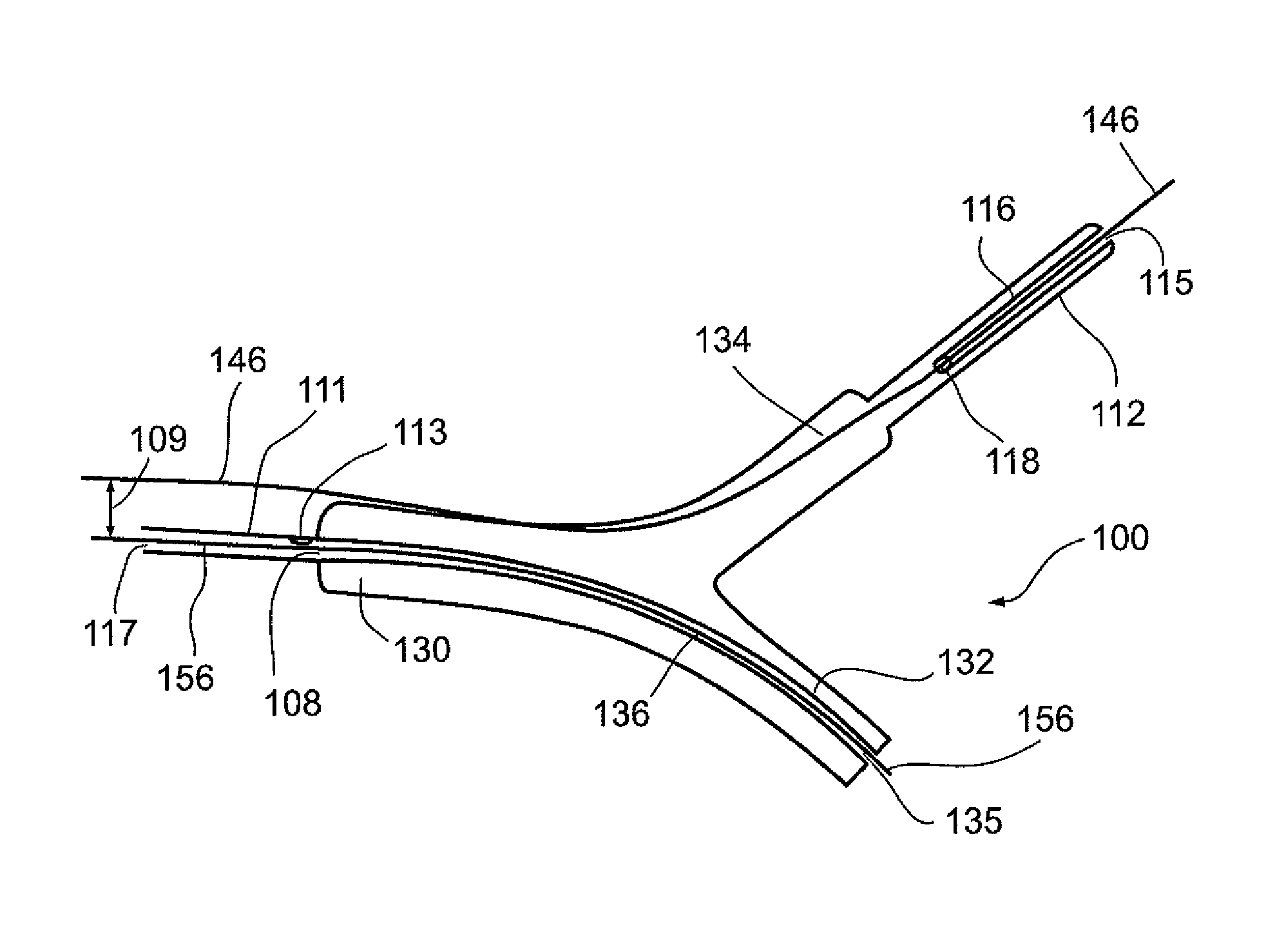
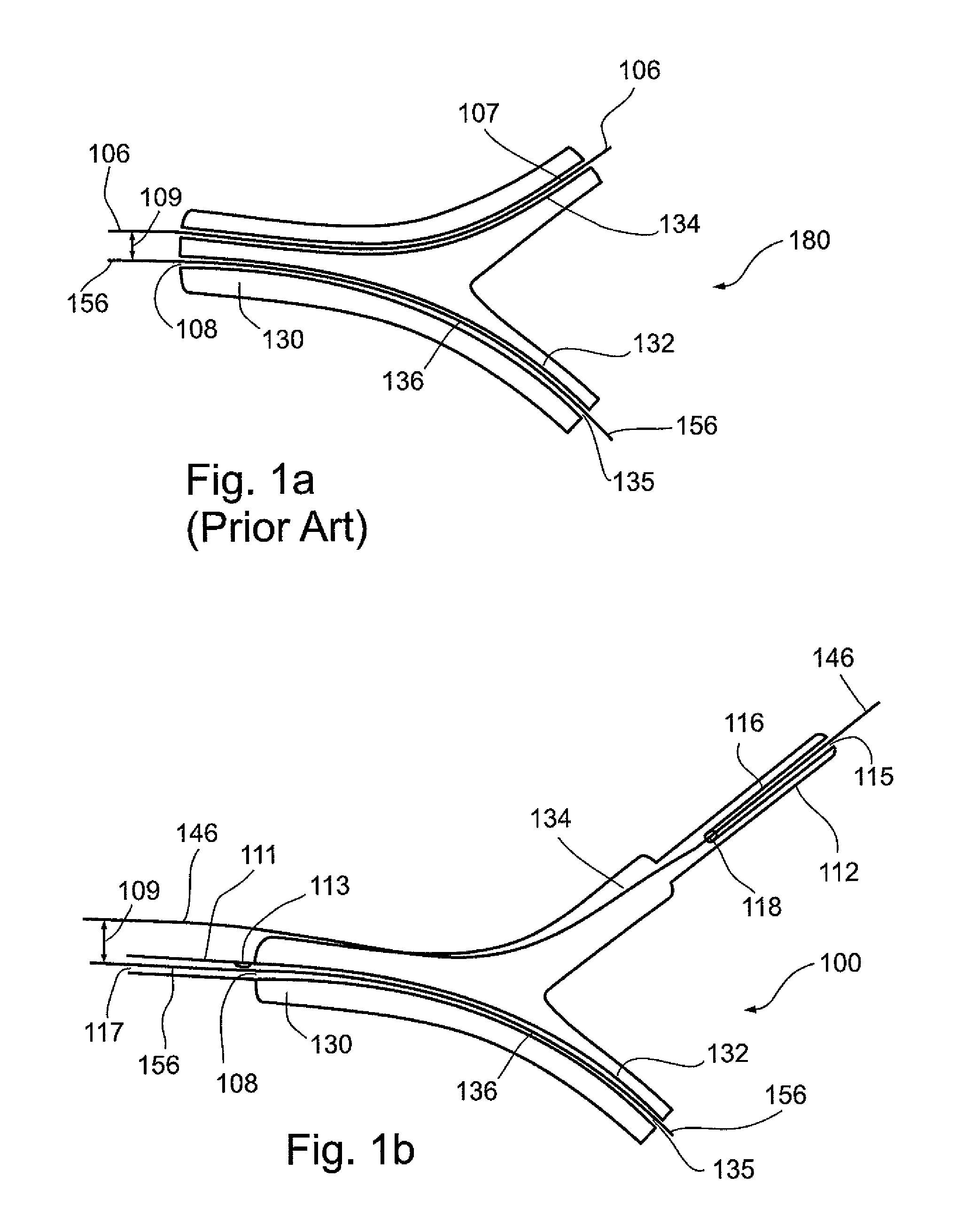
[0024]The present invention successfully addresses at least some of the shortcomings of prior art by providing a bifurcated balloon wherein there is a maximum of one guidewire lumen passing through the bifurcated balloon; thereby substantially reducing balloon crossing profile, manufacturing complexity and production cost.
[0028]When deployed with a stent having a single trunk and two distal bifurcating stent portions, the low bulk of the bifurcated balloon allows greater compaction of the stent in the unexpanded state, accruing precise balloon and stent placement and rapid deployment that ensures the patency of the bifurcated vessels.
[0047]The present embodiments successfully address the shortcomings of the presently known configurations by providing a bifurcated balloon wherein there is a maximum of a single guidewire lumen passing through the bifurcated balloon; thereby substantially reducing balloon crossing profile, manufacturing complexity and production cost.

Problems solved by technology

The precise positioning of the balloon against the constricted vessel segment is critical to the success of the procedure; yet, many factors can adversely affect balloon deliverability and precise positioning.
The human vascular tree is far from being uniform in structure and each procedure is a unique experience requiring considerable manual dexterity.
With currently available balloon systems, certain lesions are inaccessible and / or exceedingly difficult to reach due to vessel narrowing and rigidity of the treated vessel and lesions.
Vascular balloon dilation is more challenging when the constricted vessel segment is located within a bifurcation in the vessel: where a sizable side branch vessel bifurcates off a main branch vessel.
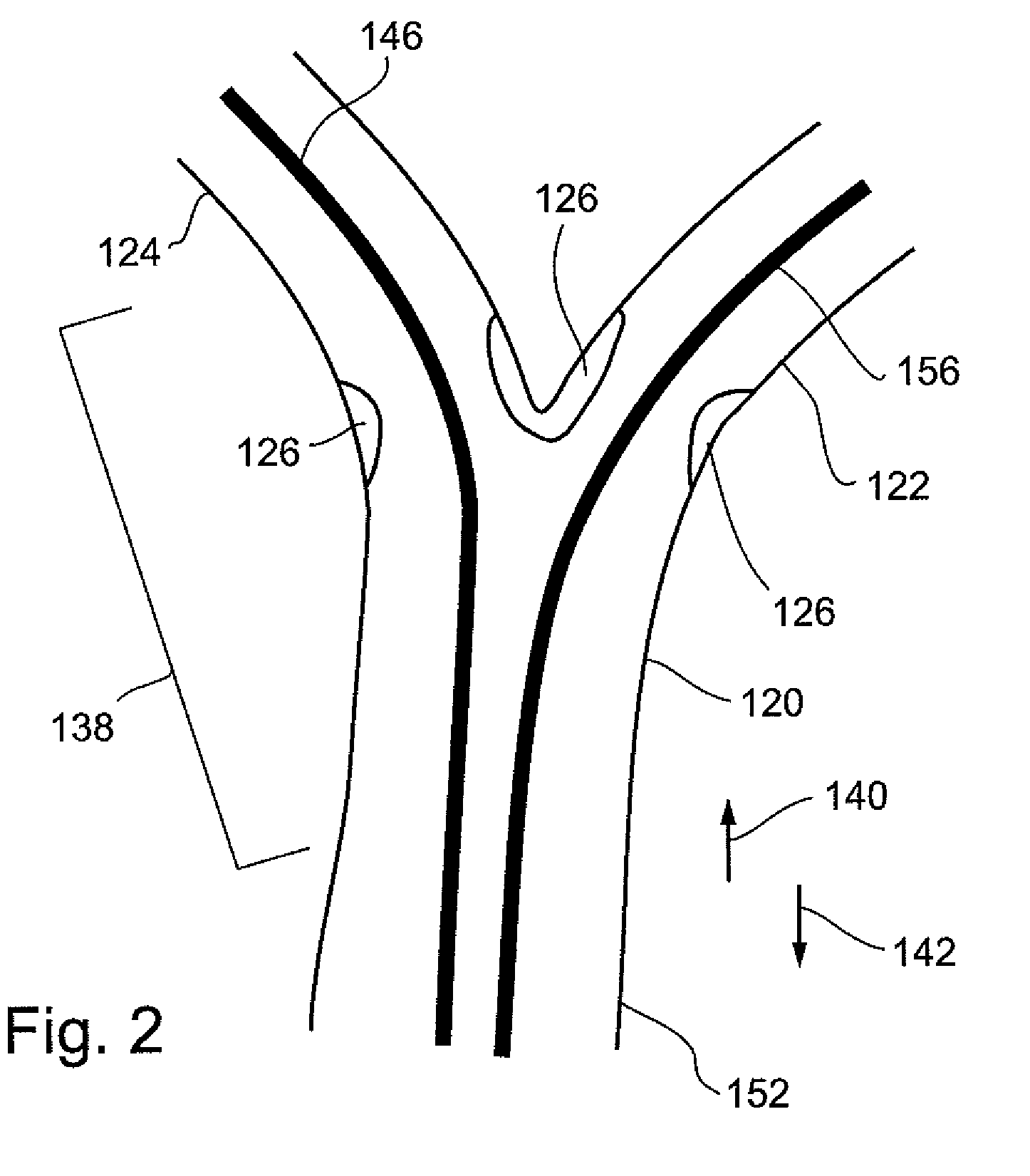
Unfortunately, sequential dilatations are frequently ineffective in treating bifurcated constricted vessels, as the vessel wall at the bifurcation tends to stretch outward; resulting in narrowing of the adjacent branch or shifting atherosclerotic debris from one vessel to the other, referred to as “shifting plaque”.
a) difficulty of coordinating inflation and deflation of two separate balloons using two separate inflators by two operators;
b) creation of asymmetric and non-circular expansion of the proximal main branch (MB) where the “kissing” takes place, potentially causing suboptimal post-inflation results. For example, underexpansion will fail to properly clear the stenotic segments; while overexpansion can cause a dissection (tear) of the vessel wall.
c) balloon slippage during inflation;
d) difficulty in positioning the side-by-side balloon segments due to the large crossing profile created by the separate guidewires and guidewire lumens in each balloon; and
e) difficulty in manipulating the guiding catheters as the catheters must accommodate two separate side-by-side balloons of at least 6 French (2.0 millimeters) or 7 French (2.3 millimeters).
However, when guidewires 106 and 156 are fed through guidewire lumens 136 and 107 respectively, the large crossing profile hinders deliverability and accurate positioning of bifurcated balloon 180.

Method used


Image

  • Bifurcated balloon & stent delivery system
  • Bifurcated balloon & stent delivery system
  • Bifurcated balloon & stent delivery system

Examples


Embodiment Construction

[0062]The present embodiments concern a bifurcated balloon having, at any given cross section throughout the length of the bifurcated balloon, a maximum of one guidewire lumen, thereby accruing a bifurcated balloon having a low bulk that is easily maneuvered through the vasculature.

[0063]The principles and operation according to the present invention may be better understood with reference to the drawings and accompanying descriptions.

[0064]Before explaining at least one embodiment of the invention in detail, it is to be understood that the invention is not limited in its application to the details of construction and the arrangement of the components set forth in the following description or illustrated in the drawings. The invention is capable of other embodiments or of being practiced or carried out in various ways.

[0065]Also, it is to be understood that the phraseology and terminology employed herein is for the purpose of description and should not be regarded as limiting.

[0066]...


PUM


Abstract

A bifurcated balloon for in vivo use, comprises: a proximal hollow tubular element, two bifurcating hollow tubular elements extending distally from a distal end of the proximal hollow tubular element, each of the two elements comprising: a first distal tubular element guidable into a first branch of a vessel bifurcation, and a second distal tubular element guidable into a second branch of the vessel bifurcation. The bifurcated balloon further comprises a longitudinal chamber extending from a distal end of the first distal tubular element, and a first substantially longitudinal guidewire channel passing through the longitudinal chamber, the first guidewire channel having two ends of which a first end passes through a proximal portion of the longitudinal chamber.

Description

RELATED APPLICATIONS[0001]This Application is a National Phase of PCT Patent Application No. PCT / IL2008 / 000242 having International filing date of Feb. 26, 2008, which claims the benefit of U.S. Provisional Patent Application No. 60 / 929,099 filed on Jun. 13, 2007. The contents of the above Applications are all incorporated herein by reference.FIELD AND BACKGROUND OF THE INVENTION[0002]The present invention relates to endovascular balloons used to recanalize, dilate and / or deploy a stent within a constricted vessel.[0003]Balloon angioplasty for opening a constricted segment of a blood vessel has become a widely accepted therapeutic alternative to coronary and peripheral arterial bypass surgery for many patients.[0004]To deliver a balloon catheter used in balloon angioplasty, a guidewire is advanced through the vasculature across the constricted vessel segment. A dedicated guidewire lumen in the balloon portion of the catheter is fed over the guidewire; the dedicated lumen substantial...

Claims


Application Information

Patent Timeline
Patent Type & Authority Patents(United States)
IPC IPC(8): A61M29/00A61F2/06A61F2/86
CPCA61F2/954A61F2/958A61M25/10A61F2/86A61F2002/065A61M2025/1045
Inventor KALUSKI, EDO
Owner KALUSKI EDO
Learn More