
Compliant seal structures for protected active metal anodes

a technology of active metal anodes and compliant seals, which is applied in the direction of non-aqueous electrolyte cells, cell components, conductors, etc., can solve the problems of reducing the ionic contact area between the active metal anode and the protective membrane architecture with subsequent performance degradation, degrading performance, and disrupting electrical communication between the two

Active Publication Date: 2011-11-01
POLYPLUS BATTERY CO INC
View PDF61 Cites 48 Cited by
  • Summary
  • Abstract
  • Description
  • Claims
  • Application Information

AI Technical Summary

Benefits of technology

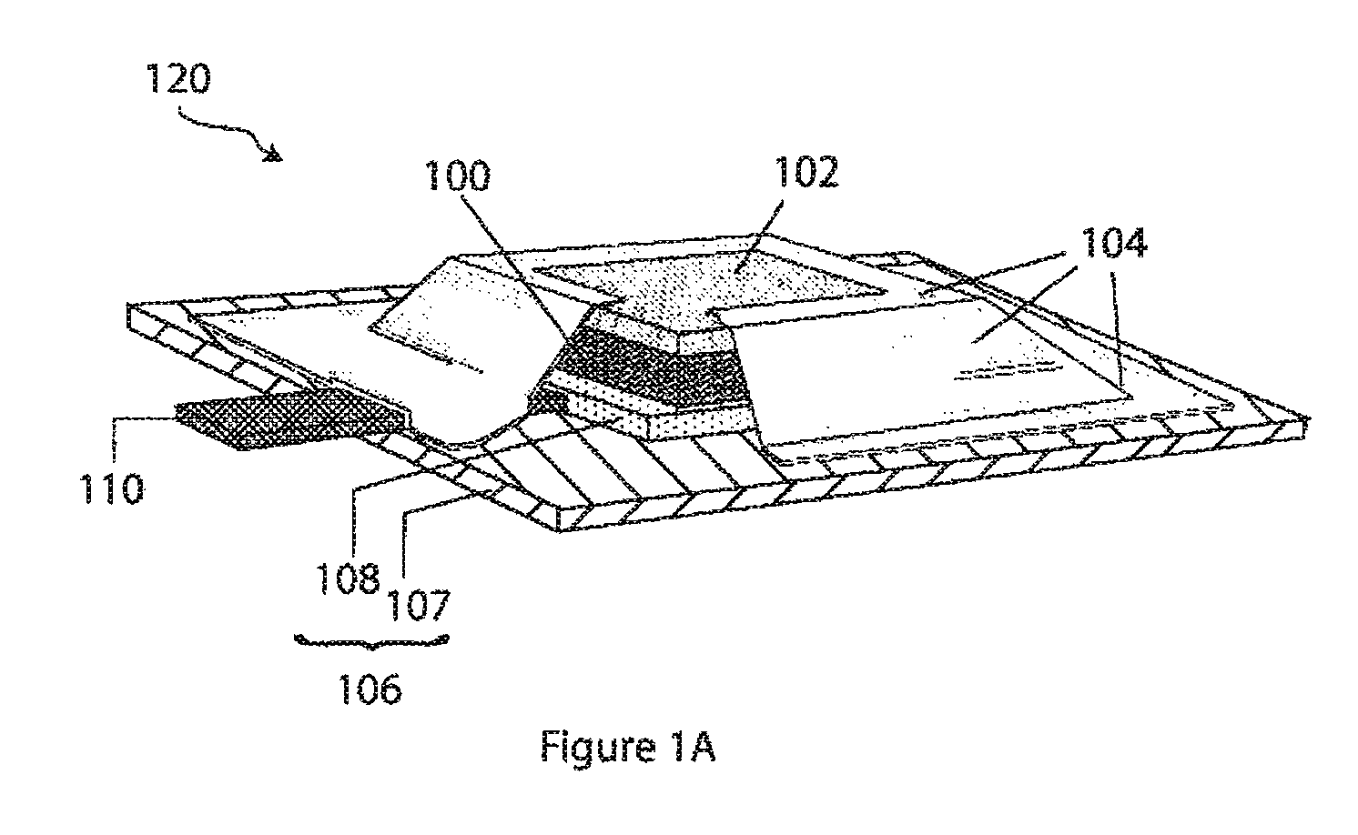
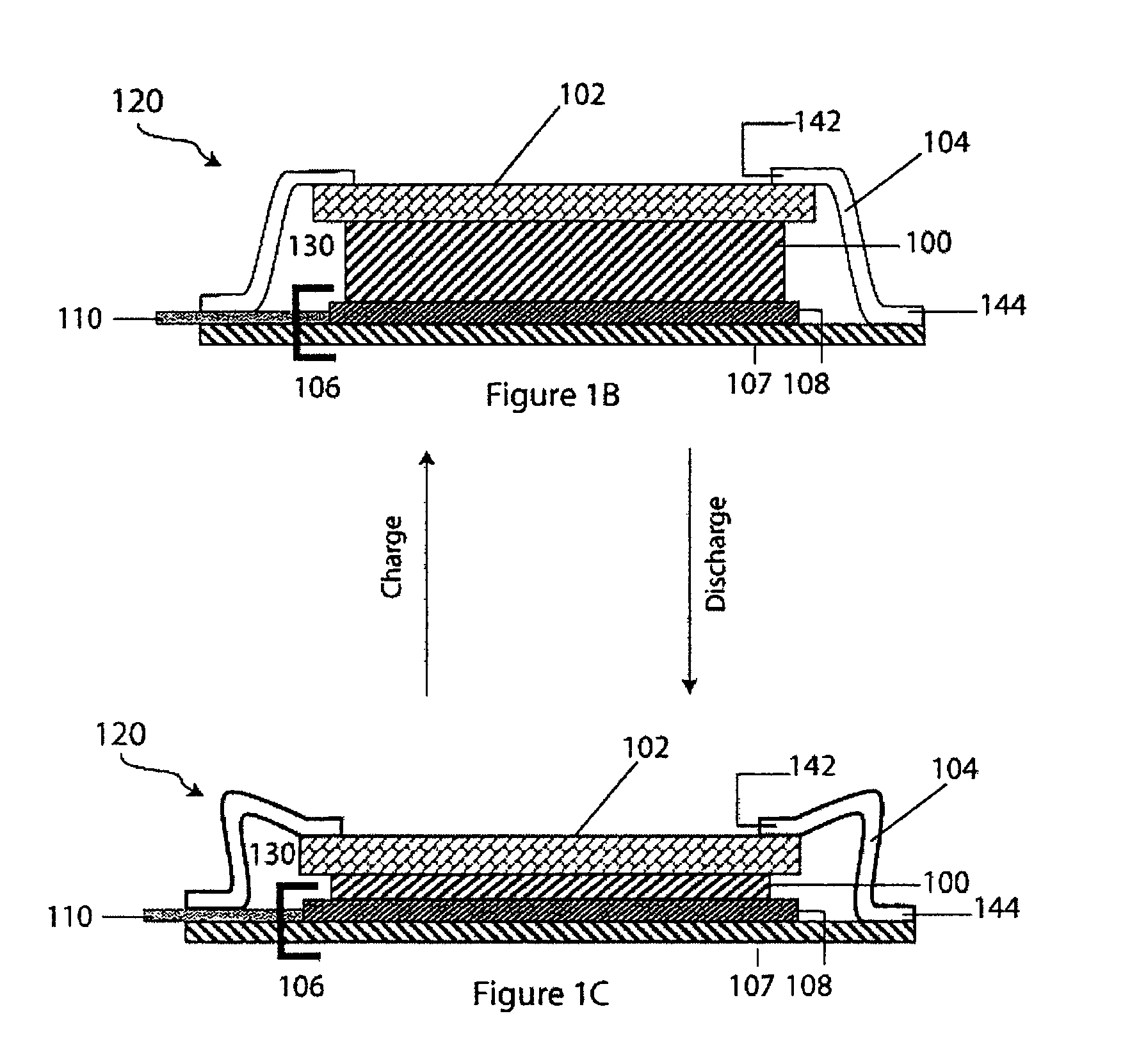
The present invention provides a protected anode architecture for batteries that prevents damage to the anode from external environments and maintains performance. The architecture includes an active metal anode, an ionically conductive protective membrane architecture, an anode backplane, and a compliant seal structure that encases the anode. The seal structure is compliant to changes in anode thickness and provides a barrier between the anode and external environments. The architecture also compensates for changes in anode volume during charging and discharging of the battery. The technical effects of the invention include improved performance, reduced interfacial gaps, and enhanced cell structure compactness.

Problems solved by technology

If this volume decrease is not compensated in some manner, interfacial gaps between the active metal anode and the protective membrane architecture could result, leading to reduced ionic contact area between the active metal anode and protective membrane architecture with subsequent performance degradation.
Similar gaps or voids between the active metal anode and backplane can also degrade performance where the backplane is or includes the anode current collector and electrical communication between the two is disrupted.

Method used


Image

  • Compliant seal structures for protected active metal anodes
  • Compliant seal structures for protected active metal anodes
  • Compliant seal structures for protected active metal anodes

Examples


example 1

Demonstration of Effectiveness of Compliant Seal

[0270]A commercial multi-layer laminate material (MLLM) with the product specification Laminate 95014 (manufactured by Lawson Mardon Flexible, Inc. in Shelbyville, Ky.) was used to make a compliant, hermetic seal to a lithium ion conducting glass-ceramic (GC) membrane. In this case, as well as in all the examples described below, we used the GC membranes, developmental product AG-01, supplied to PolyPlus by the OHARA Corporation. The ionic conductivity of the GC membrane was in the range of (1.0-1.5)×10−4 S / cm. The membrane was a 1″×1″ square with a thickness of 150 micrometers.

[0271]The MLLM product Laminate 95014 has a thickness of 118-120 μm and is made of:[0272]PET—Polyethylene terephthalate, 12 μm[0273]ADH—a two-part polyurethane adhesive[0274]Aluminum foil, 32 μm[0275]EAA—Ethacrylic acid (a primer for the aluminum foil; also improves wetting between LDPE and PET)[0276]PET—Polyethylene terephthalate, 12 μm[0277]LDPE—Low density po...

example 2

Testing of Double-Sided Protected Lithium Anode with Compliant Seal in Seawater Electrolyte

[0282]The same method and equipment as described in Example 1 were used to bond the GC membrane (substantially impervious, ionically conductive layer) surface with the MLLM having a square hole of 22 mm×22 mm. The width of the bond was approximately 1.7 mm. Two such structures were fabricated and then sealed together on three of their sides by bonding the bottom LDPE layers of the MLLMs to each other. The impulse heat-sealer Model 14A / A-CAB (Vertrod Corp.) with modified jaws was used for this operation. The resulting open-ended bag had two GC plates bonded to the MLLMs.

[0283]A lithium electrode was fabricated in the dry room by pressing two square 22 mm×22 mm pieces of Li foil with a nominal thickness of 0.6 mm (FMC Lithium Inc.) on both sides of Ni foil current collector having the same dimensions and a thickness of 50 μm. The pressing operation was performed in a die with polypropylene block...

example 3

Long-Term Testing of Double-Sided Protected Lithium Anode with Compliant Seal in Aqueous Electrolyte Used in Li / Air Cells

[0292]In this example, the compliant seal structure included an inorganic layer of SnNx in the bonded area of the GC surface.

[0293]Pre-Forming the MLLM

[0294]In this case, the MLLM was molded into a preformed frame. Such performing allows for use of significantly thicker Li foils compared to those used with the unformed MLLMs. Also, it ensures more uniform shrinking (collapsing) of the compliant seal during anode discharge. One more benefit is the potential reduction of the wasted volume of the anode compartment, depending on the frame geometry.

[0295]In the first step a square 43 mm×43 mm sheet of MLLM was molded into the shape 1 shown in FIG. 17A using a steel die and applying a pressure of 500 kg. The height H was approximately 1.2 mm and the width of the top W1 was 26 mm. The edges of the bottom step were cut, making its width W2 equal to 2 mm. The bottom openin...


PUM

PropertyMeasurementUnit
distanceaaaaaaaaaa
thicknessaaaaaaaaaa
thicknessaaaaaaaaaa

Abstract

Protected anode architectures have ionically conductive protective membrane architectures that, in conjunction with compliant seal structures and anode backplanes, effectively enclose an active metal anode inside the interior of an anode compartment. This enclosure prevents the active metal from deleterious reaction with the environment external to the anode compartment, which may include aqueous, ambient moisture, and / or other materials corrosive to the active metal. The compliant seal structures are substantially impervious to anolytes, catholytes, dissolved species in electrolytes, and moisture and compliant to changes in anode volume such that physical continuity between the anode protective architecture and backplane are maintained. The protected anode architectures can be used in arrays of protected anode architectures and battery cells of various configurations incorporating the protected anode architectures or arrays.

Description

CROSS-REFERENCE TO RELATED APPLICATIONS[0001]This application is a continuation-in-part of U.S. patent application Ser. No. 11 / 501,676 filed Aug. 8, 2006, titled COMPLIANT SEAL STRUCTURES FOR PROTECTED ACTIVE METAL ANODES, now U.S. Pat. No. 7,824,806; which claims priority to Provisional Application No. 60 / 706,886 filed Aug. 9, 2005, titled ELASTOMERIC SEALS FOR PROTECTED ACTIVE METAL ANODES, and U.S. Provisional Application No. 60 / 713,668 filed Sep. 2, 2005, titled ADHESIVE SEALS FOR PROTECTED ACTIVE METAL ANODES; the disclosures of which are incorporated by reference herein.BACKGROUND OF THE INVENTION[0002]The present invention relates generally to active metal electrochemical devices. More particularly, this invention relates to protected anodes architectures incorporating compliant seal structures, including single and double sided protected anodes and arrays of protected anodes, and their associated electrochemical cell structures and devices such as batteries, particularly, ac...

Claims


Application Information

Patent Timeline
Patent Type & Authority Patents(United States)
IPC IPC(8): H01M4/40H01M4/76H01M2/08H01M4/02H01M4/13H01M4/131H01M4/133H01M10/052H01M10/36H01M50/184H01M50/186H01M50/193H01M50/463
CPCH01B1/122H01M2/16H01M2/1686H01M2/18H01M4/13H01M10/34H01M12/08H01M2/08Y10T29/4911H01M4/131H01M4/133H01M6/30H01M6/42H01M10/052H01M2004/021H01M2004/027Y02E60/122Y02E60/10H01M50/463H01M50/184H01M50/186H01M50/193
Inventor VISCO, STEVEN J.NIMON, YEVGENIY S.DE JONGHE, LUTGARDKATZ, BRUCE D.PETROV, ALEXEI
Owner POLYPLUS BATTERY CO INC
Learn More