
Substrate-level assembly for an integrated device, manufacturing process thereof and related integrated device

a technology of integrated devices and substrates, applied in the direction of semiconductor electrostatic transducers, microphone structural associations, transducer casings/cabinets/supports, etc., can solve the problems of limiting monitoring to time intervals, excessive encroachment, and inconvenient use of traditional packaging techniques

Active Publication Date: 2011-11-01
STMICROELECTRONICS SRL
View PDF19 Cites 54 Cited by
  • Summary
  • Abstract
  • Description
  • Claims
  • Application Information

AI Technical Summary

Benefits of technology

The present patent provides a substrate-level assembly for integrated devices that can minimize manufacturing costs and reduce the size of the final product. The assembly includes a device substrate with a first integrated device and a capping substrate that covers the device with an empty space above it. The assembly also includes electrical-contact elements for connecting the device to external electronics. The patent also describes an electronic device that includes the substrate-level assembly and a package for protection. The manufacturing process includes providing a device substrate, forming a first integrated device, coupling a capping substrate to the device substrate, and forming electrical-contact elements. The assembly can also include a sensor for monitoring the condition of an article.

Problems solved by technology

An acceleration of intensity greater than a pre-set threshold is representative of a condition of movement of the vehicle, and consequently causes the start of pressure monitoring, so limiting monitoring to time intervals during which the vehicle is moving.
The dimensions of the sensors described are particularly small, namely, in the region of 0.8 mm×0.8 mm×0.3 mm (length×width×thickness), or in the region of 2 mm×2 mm×0.3 mm, so that traditional packaging techniques do not prove advantageous, and in particular packages of a traditional type, of a molded or pre-molded type, prove to be of excessive encumbrance and in any case not optimized for applications, such as automotive or consumer applications, which require size minimization.
Moreover, packages of the traditional type are not optimized in terms of manufacturing costs.

Method used


Image

  • Substrate-level assembly for an integrated device, manufacturing process thereof and related integrated device
  • Substrate-level assembly for an integrated device, manufacturing process thereof and related integrated device
  • Substrate-level assembly for an integrated device, manufacturing process thereof and related integrated device

Examples


Embodiment Construction

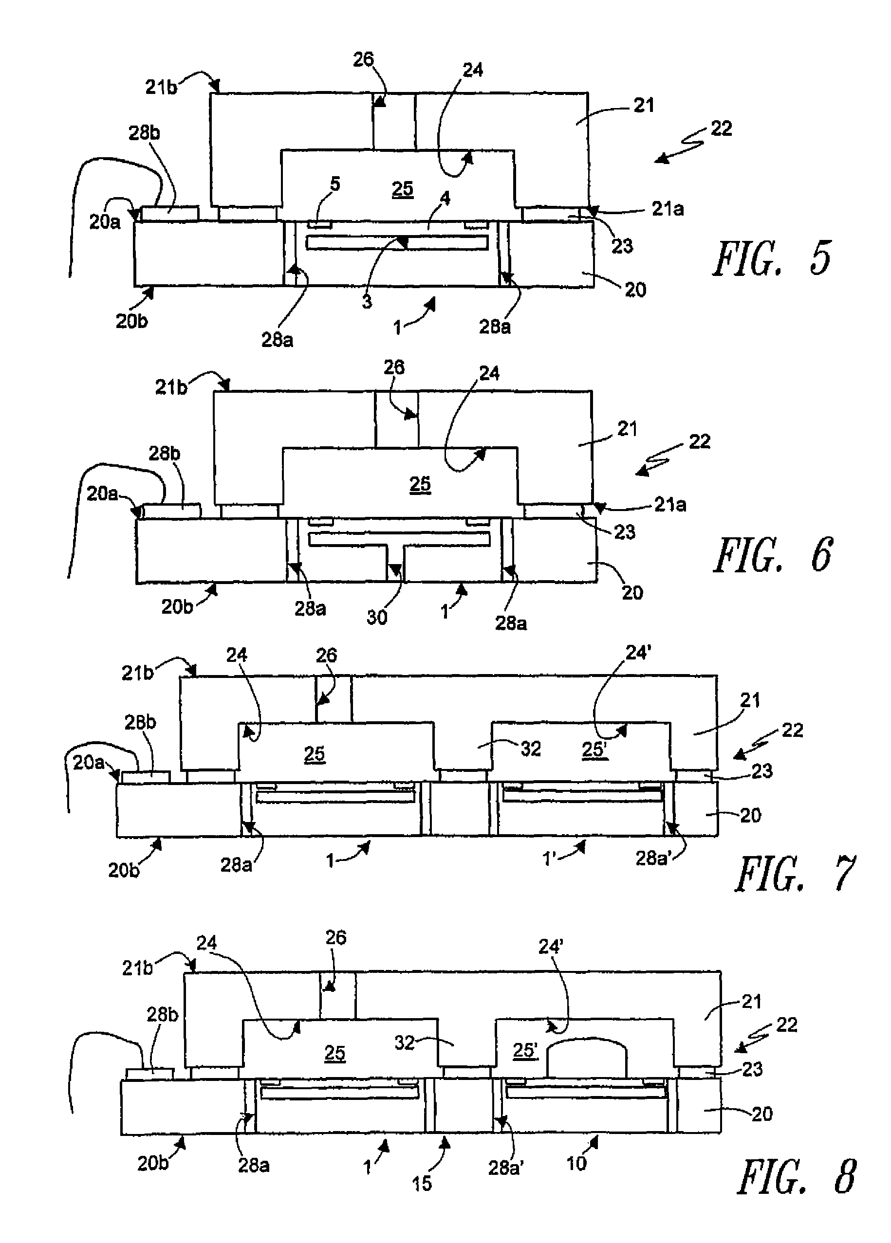
[0035]FIG. 5 shows a substrate 20 of semiconductor material, for example, monocrystalline silicon, having a top surface 20a and a bottom surface 20b, opposite to the top surface 20a (in what follows, the substrate 20 will be referred to as “device substrate,” in so far as it is designed to integrate one or more integrated devices, in particular, sensor devices).

[0036]An integrated device, namely a pressure sensor 1, is formed inside the device substrate 20, as described with reference to FIG. 1 (so that parts that are similar are designated by the same reference numbers). In particular, the membrane 4, suspended over the buried cavity 3, is formed at the top surface 20a of the device substrate 20.

[0037]According to an aspect of the present disclosure, a capping substrate 21, made of semiconductor material (for example, silicon), glass, or other ceramic or polymeric material, is (mechanically or electrically or a combination of mechanically and electrically) coupled to the device sub...


PUM


Abstract

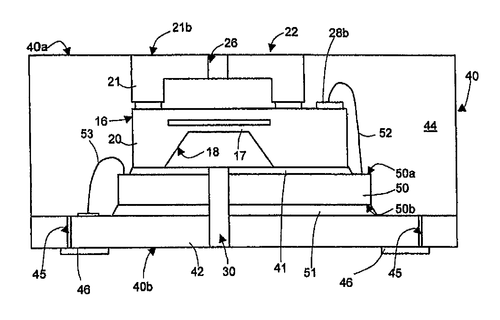
A substrate-level assembly having a device substrate of semiconductor material with a top face and housing a first integrated device, including a buried cavity formed within the device substrate, and with a membrane suspended over the buried cavity in the proximity of the top face. A capping substrate is coupled to the device substrate above the top face so as to cover the first integrated device in such a manner that a first empty space is provided above the membrane. Electrical-contact elements electrically connect the integrated device with the outside of the substrate-level assembly. In one embodiment, the device substrate integrates at least a further integrated device provided with a respective membrane, and a further empty space, fluidly isolated from the first empty space, is provided over the respective membrane of the further integrated device.

Description

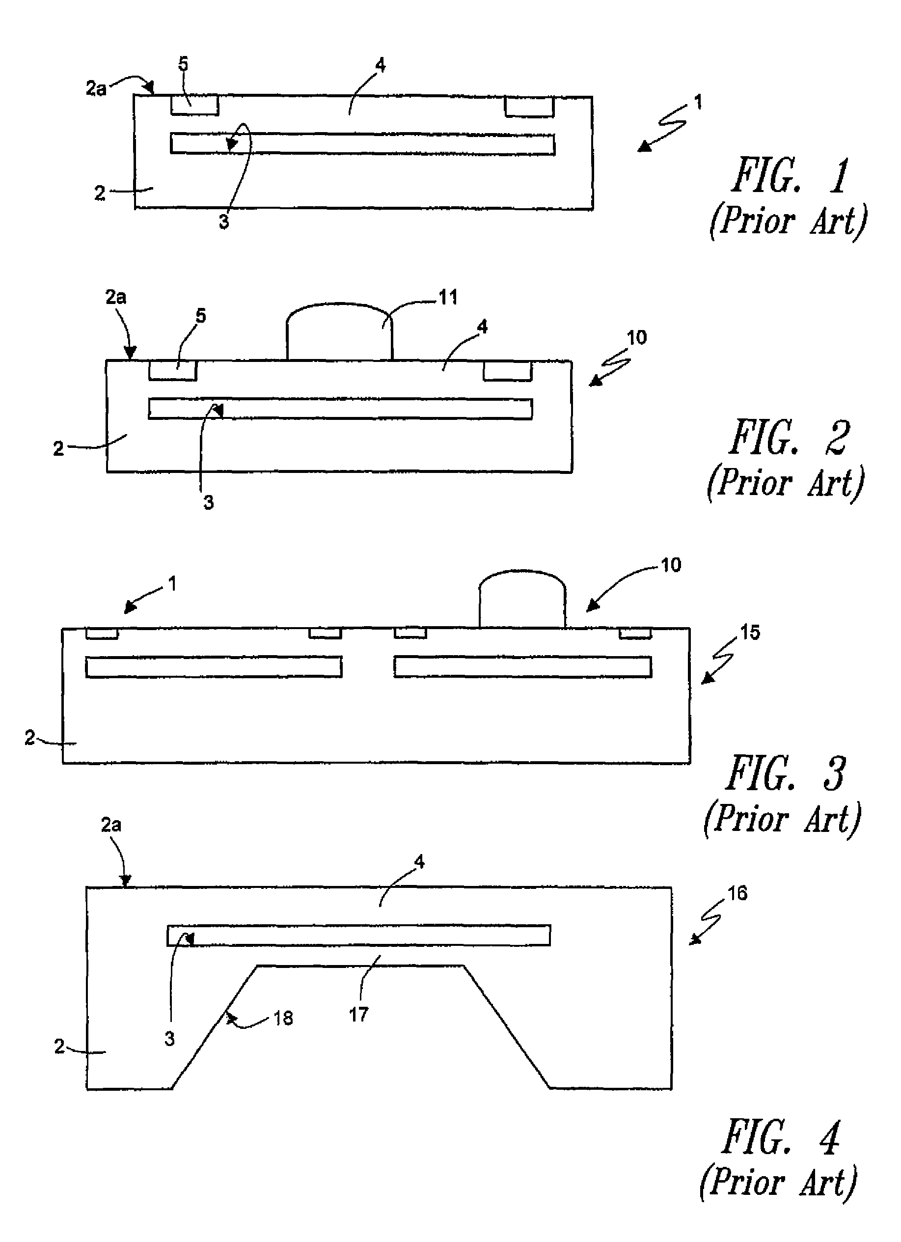
BACKGROUND[0001]1. Technical Field[0002]The present disclosure relates to a substrate-level assembly (usually known as “wafer-level package”) for an integrated device and, in particular, a sensor device, as well as to a corresponding manufacturing process and the related integrated device.[0003]2. Description of the Related Art[0004]Semiconductor sensors are known (for example, pressure sensors, inertial sensors, microphones, or gas sensors) which are made with microfabrication techniques and whose operation is based upon the presence of a membrane that is suspended over a cavity.[0005]For example, EP 1 577 656, filed in the name of the present applicant, describes a pressure sensor and a manufacturing process thereof. In detail (FIG. 1), the pressure sensor, designated by 1, is integrated in a substrate 2 made of semiconductor material, in particular monocrystalline silicon, having a top surface 2a. A buried cavity 3 is formed within the substrate 2, and is separated from the top s...

Claims


Application Information

Patent Timeline
Patent Type & Authority Patents(United States)
IPC IPC(8): H01L29/84
CPCB81B7/0061B81B7/02H04R19/005B81B2201/0264H04R1/04B81B2201/0235B81C1/0023H01L2224/48091H01L2224/73265H01L2924/1461H01L2924/3025H01L2924/00014H01L2924/00
Inventor COMBI, CHANTALVIGNA, BENEDETTOZIGLIOLI, FEDERICO GIOVANNIBALDO, LORENZOMAGUGLIANI, MANUELALASALANDRA, ERNESTORIVA, CATERINA
Owner STMICROELECTRONICS SRL
Learn More