CAD modeling system and method

a modeling system and model technology, applied in static indicating devices, instruments, image data processing, etc., can solve the problems of inaccurate replacement parts produced from models, difficult to assemble onto existing parts, and difficult automation of modeling processes, so as to reduce scanning speed, increase scanning speed, and accurate reproduction

Active Publication Date: 2011-11-01
RTX CORP
View PDF5 Cites 26 Cited by
  • Summary
  • Abstract
  • Description
  • Claims
  • Application Information

AI Technical Summary

Benefits of technology

[0008]The present invention is directed to a system and method for generating a 3D model of an object. The system includes cameras, a 3D scanner, and at least one image processor that processes both 2D and 3D images. The cameras first capture a 2D image of the object to be modeled and breaks the 2D image into its constituent geometric elements. The 3D scanner then scans the object and generates a 3D stereoscopic image depicting the object. The scanner may adjust its scanning process based on the feature-richness of the object, such as reducing the scanning speed if the object contains many geometric elements and features and increasing the scanning speed if the object is made of only a few simple geometric elements. The 3D stereoscopic image is fitted to the geometric elements generated from the 2D image to generate the final model.
[0009]In one embodiment, the 3D stereoscopic image is compared with the possible geometric elements in the 2D image to detect distortions in the object. These distortions may then be automatically removed to ensure that the generated model does not duplicate the distortions but faithfully reflects the original design intent. Thus, the invention can generate a model that is a more accurate reproduction even compared to the original physical object from which the model is generated.

Problems solved by technology

This manual process tends to be very time-consuming and error prone.
Further, if the master part is distorted and / or has additional features like holes, slots, etc. on distorted surfaces, the manual process will introduce these errors into the model, making replacement parts produced from the model inaccurate and difficult to assemble onto existing parts.
This is also a time-consuming, error-prone process because the drawings may not be accurate or complete and do not reveal connectivity relationships between features, making automation of the modeling process difficult.
In cases where the original part has been modified onsite to solve an assembly problem, these modifications are often not reflected in the master drawing, making replacement parts made from the drawing unfit for proper assembly.
This results in a sculpted surface and not a regular geometric surface.
Thus, the tool path produced using this method will be useful for machining sculpted surfaces and not for regular geometric surfaces because the tool path created is more complex and, paradoxically, more error-prone due to the distortions in the resulting model.
Thus, the scanning system requires a complex multi-axis machine to reproduce even simple surfaces.
Deriving a simpler CAD model out of this to reproduce the standard geometric surfaces adds further complexity to the modeling process.

Method used


Image

  • CAD modeling system and method
  • CAD modeling system and method
  • CAD modeling system and method

Examples


Embodiment Construction

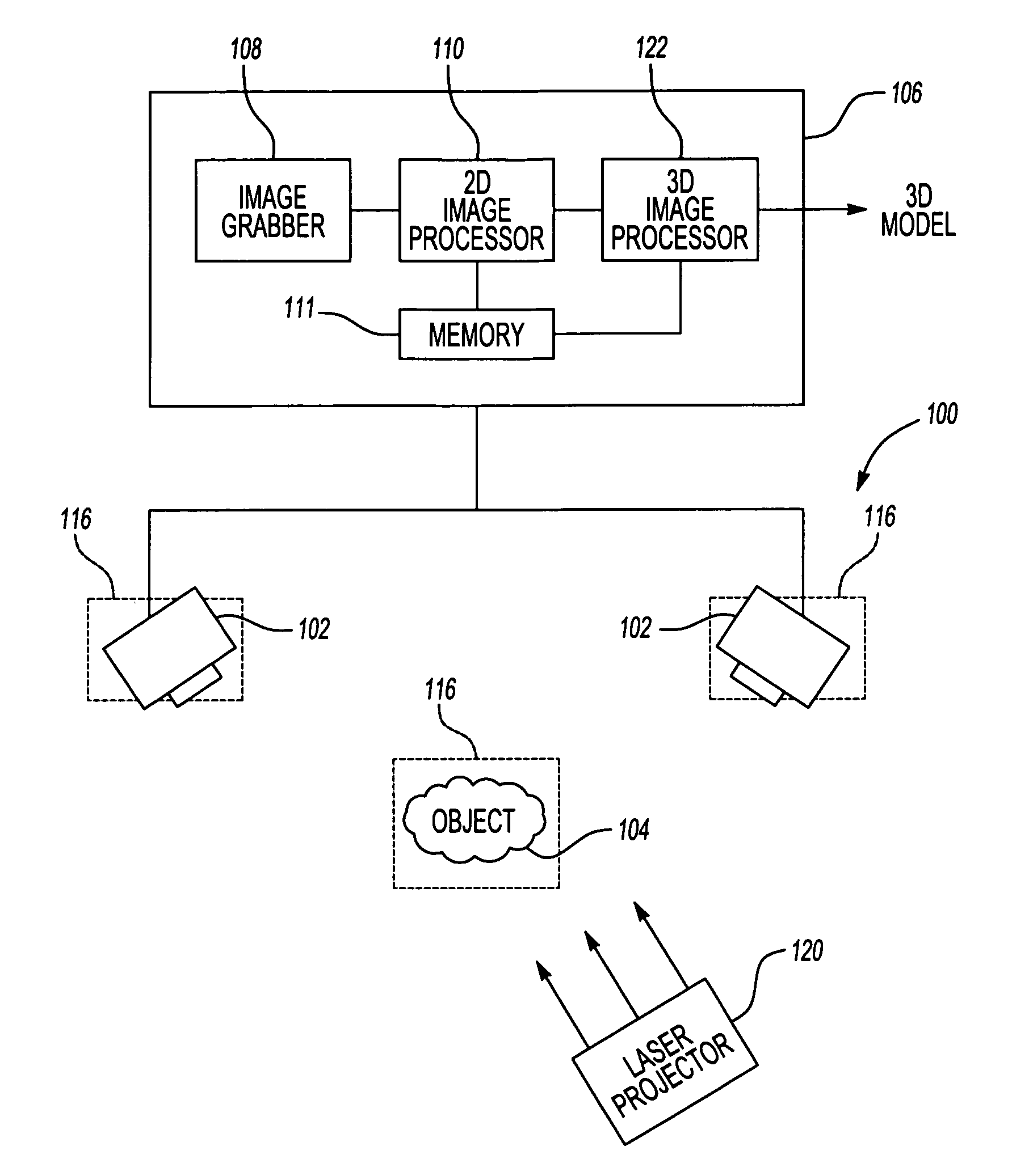
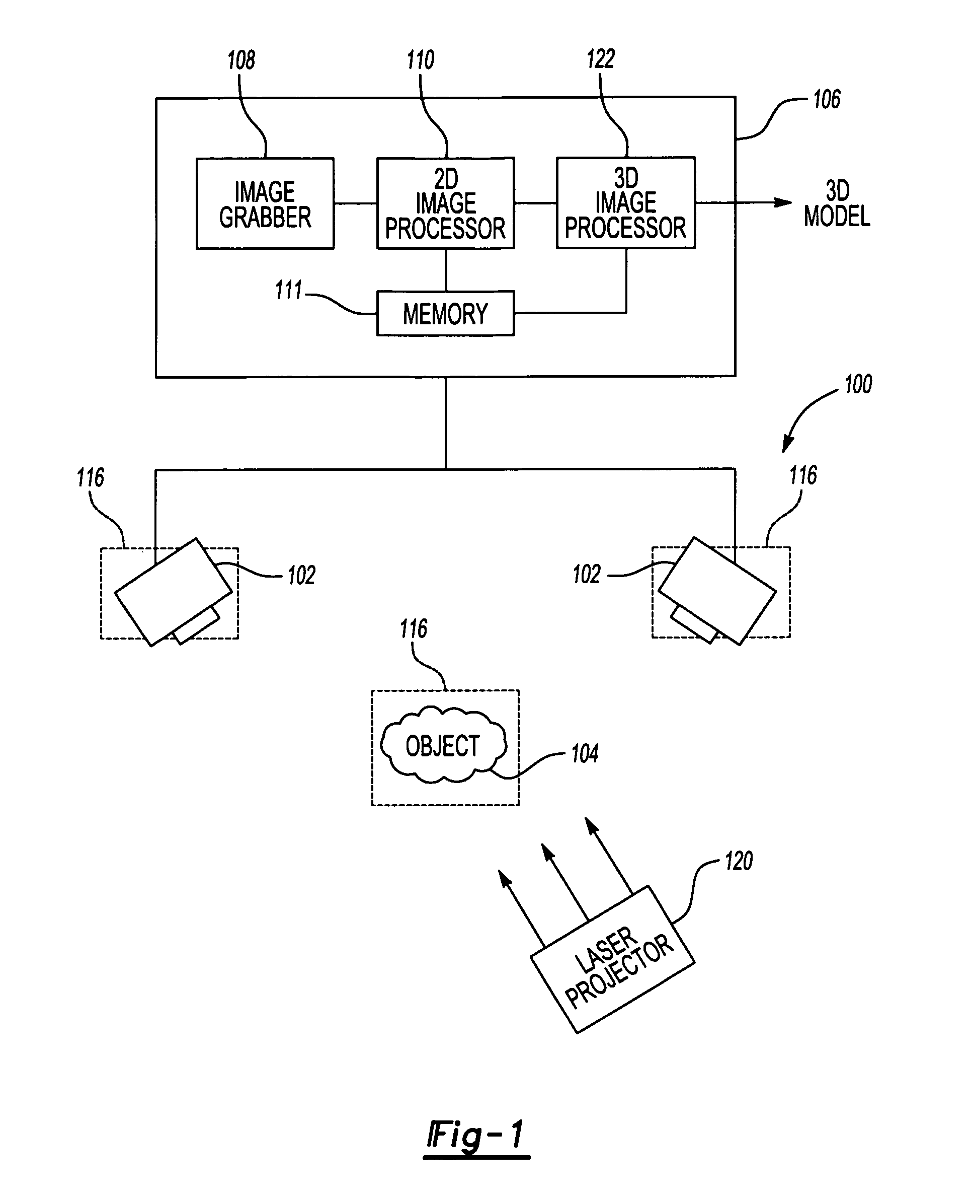
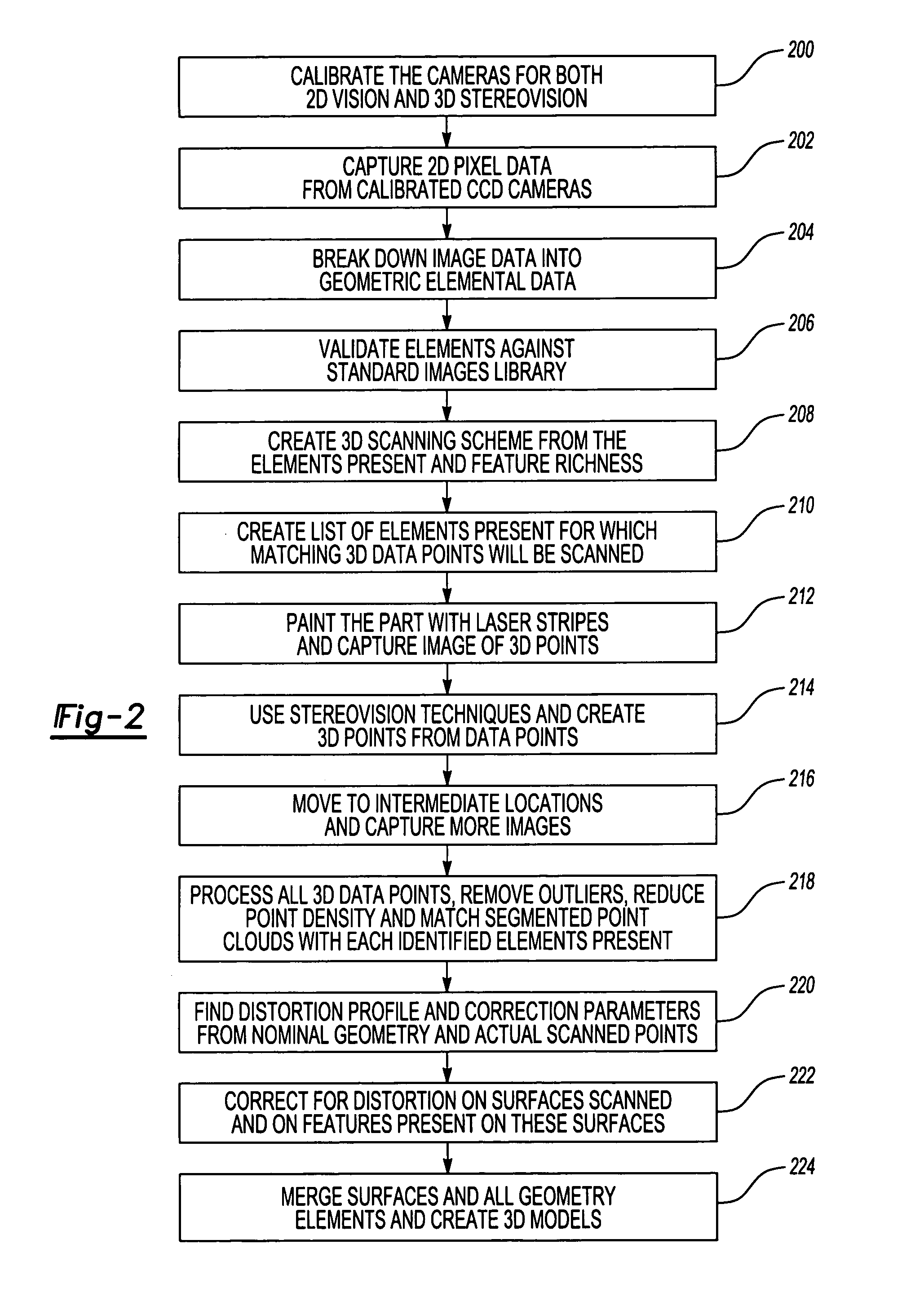
[0012]The invention is generally directed to a 3D modeling method and system that automatically creates a full 3D CAD model of regular featured geometry sheet metal items quickly and automatically. Unlike scanning systems for complex airfoil shapes, which interprets each point and creates a sculpted surface, this process automatically creates full CAD models that are the exact replica of the original regular geometry. This process also automatically corrects and compensates for distortions in the scanned surfaces, placing any holes and other localized features in the correct location in an undistorted surface in the generated model.

[0013]FIG. 1 is a representative block diagram illustrating components of a modeling system 100 according to one embodiment of the invention. In one embodiment, the system 100 a 2D gray-tone vision system was integrated with a 3D scanning system. Generally, the system 100 avoids the extensive processing resources needed in currently-known modeling systems...


PUM


Abstract

A 3D object modeling system and method system and method captures a 2D representation of the object to be modeled and breaks the 2D image into its geometric elements. The 3D stereoscopic image is then fitted to the geometric elements generated from the 2D image to generate the final model. The 3D stereoscopic image may be compared with the geometric elements to detect distortions in the object, allowing the distortions to be corrected in the final model to ensure that the model accurately depicts the original object.

Description

TECHNICAL FIELD[0001]The present invention relates to computer assisted design (CAD) system and methods, and more particularly to CAD systems and methods that create a CAD model of an existing object.BACKGROUND OF THE INVENTION[0002]Designing replacement parts, such as aircraft engine and helicopter airframe sheet metal parts, require accurate three-dimensional (3D) CAD models to provide an accurate tool path for machining the replacement parts. Ideally, the 3D CAD model precisely defines all the geometric elements in a given part, their dimensions and the connectivity relationships between them.[0003]One known 3D CAD modeling technique involves measuring an existing master part and creating a CAD model manually from the measured dimensions. This manual process tends to be very time-consuming and error prone. Further, if the master part is distorted and / or has additional features like holes, slots, etc. on distorted surfaces, the manual process will introduce these errors into the m...

Claims


Application Information

Patent Timeline
Patent Type & Authority Patents(United States)
IPC IPC(8): G06K9/00G01B11/245G06F17/50G06T1/00G06T3/00G06T17/00G06T17/10G06T19/00
CPCG06T7/0057G06T7/0075G06T17/10G06T2200/08G06T7/521G06T7/593
Inventor VAIDYANATHAN, JANAKIRAMAN
Owner RTX CORP
Why Eureka
Try Eureka