Annular rotary platform for a milking parlour, a mould and method for manufacturing of such a platform

a technology of rotary platform and milking parlour, which is applied in the field of annular rotary platform for milking parlour, can solve the problems of needing conventional ribs or frameworks of relatively expensive materials, and achieve the effect of easy water and dirt washing off and simple cleaning of the platform

Active Publication Date: 2011-11-08
DELAVAL HLDG AB
View PDF32 Cites 5 Cited by
  • Summary
  • Abstract
  • Description
  • Claims
  • Application Information

AI Technical Summary

Benefits of technology

[0005]The object of the present invention is to achieve a rotary platform for a milking parlour, which has a reliable function, a good strength and is possible to manufacture to a relatively low cost.
[0006]This object is achieved by the rotary parlour initially defined, which is characterised in that the platform on an underside comprises at least one protruding reinforcing portion formed of a cementitious material. The cementitious material may be concrete. The platform achieves in an area provided with such a protruding reinforcing portion of a cementitious material an increased thickness and an increased strength. The protruding reinforcing portion on the underside of the platform may be provided with a suitable design in order achieve a desired strength in different areas and directions of the platform. Preferably, the protruding reinforcing portion and the remaining part of the platform are formed during the same casting process of the cementitious material. Thereby, it is possible to manufacture the platform in a quick and easy manner. Furthermore, the existence of such a protruding reinforcing portion of a cementitious material on the underside of the platform reduces the need of conventional ribs or frameworks of relatively expensive materials such as steel. Consequently, the platform will be manufactured to a relatively low cost.
[0007]According to an embodiment of the invention, said protruding reinforcing portion has an elongated shape on the underside of the platform. Thereby, it is possible to provide the platform with an increased strength in the direction of the elongated reinforcing portion. Said protruding reinforcing portion may have an extension in a substantially radial direction on the underside of the annular platform. The platform is quite rigid but in this manner the annular platform will be somewhat stiffer in a radial direction than in a direction along its circular extension. The platform may comprise a plurality of such protruding reinforcing portions arranged in different positions on the underside of the platform. Thereby, it is possible to provide the platform with an increased strength in different areas located at a distance from each other. Preferably, adjacent protruding reinforcing portion are arranged at substantially equal distances from each other on the underside of the platform. Thereby, it is possible to give the floor in the milking stalls on the upper side of the annular platform a substantially corresponding strength.
[0010]According to a further embodiment of the invention, the platform comprises at least one reinforcing element cast into the cementitious material. The reinforcing element may constitute one or several reinforcement bar. A reinforcing element of a strength metal material embedded in a cementitious material supplies a considerable strength to the platform. The reinforcing elements may be elongated and have an extension in a radial direction of the platform in order to further increase the stiffness of the platform in this direction. The protruding reinforcing portion may comprise at least one reinforcing element cast into the cementitious material. Thereby, the strength of the protruding reinforcing portion will be considerably increased. The upper portion of the connecting member, which is embedded in the cementitious material, may be connected to one or several of the reinforcing elements by means of, for example, welding. Thereby, the weight from the platform and the cows standing on the platform will be transferred from the reinforcing element, via the connecting member, to the circular rail member.
[0012]According to a further embodiment of the invention the annular platform has an upper surface with an inner circumference edge located at a higher level than an outer circumference edge. Preferably, the annular platform has a plane upper surface sloping about 3° in relation to a horizontal plane. This simplifies the cleaning of the platform because water and dirt rinse off easily. Such a sloping of the platform is preferred if the milking members are attached by operators working from the outside of the platform. Alternatively, the annular platform has an upper surface with an inner circumference edge located at a lower level than an outer circumference edge. Such a sloping of the platform is preferred if the milking members are attached by operators working from the inside of the platform.

Problems solved by technology

Furthermore, the existence of such a protruding reinforcing portion of a cementitious material on the underside of the platform reduces the need of conventional ribs or frameworks of relatively expensive materials such as steel.

Method used


Image

  • Annular rotary platform for a milking parlour, a mould and method for manufacturing of such a platform
  • Annular rotary platform for a milking parlour, a mould and method for manufacturing of such a platform
  • Annular rotary platform for a milking parlour, a mould and method for manufacturing of such a platform

Examples


Embodiment Construction

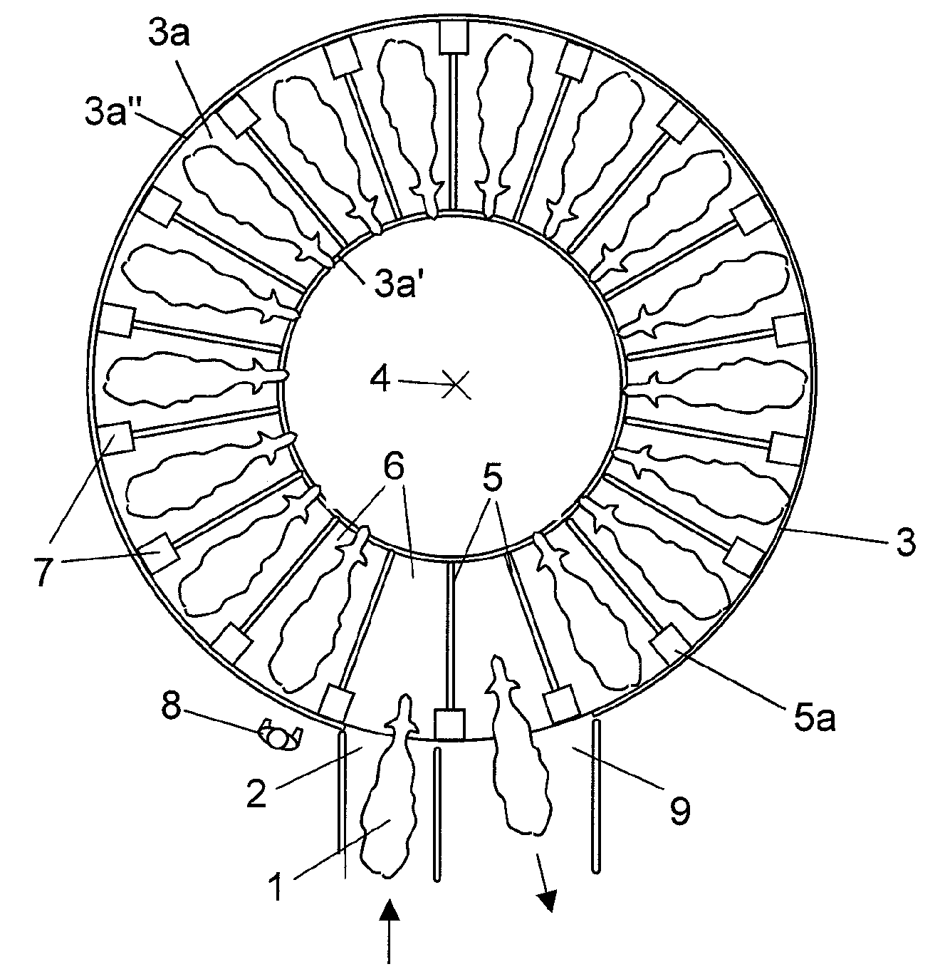
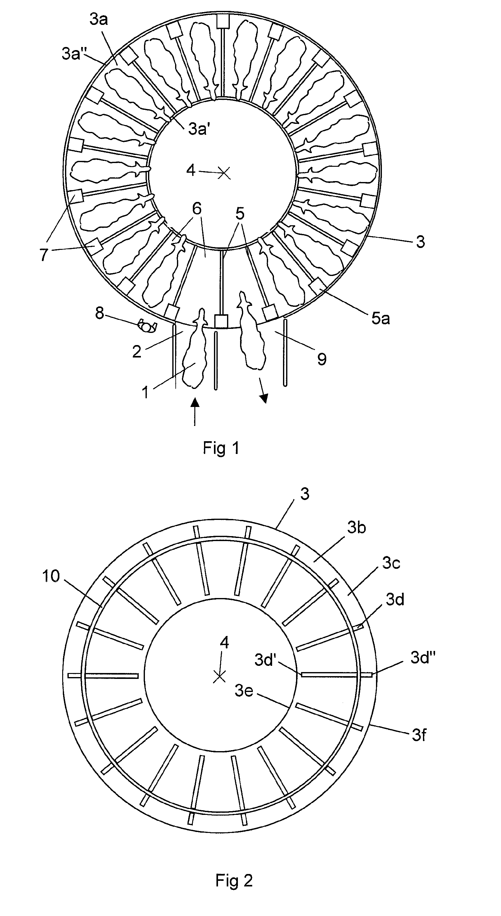
[0020]FIG. 1 shows a rotary parlour for milking of cows 1. The cows 1 to be milked are arranged to walk through an entry 2 to enter an annular platform 3. The platform 3 is rotatably arranged around a substantially vertical axis 4. The platform 3 is substantially formed of a cementitious material such a concrete. The platform 3 has a substantially plane upper surface 3a for supporting cows 1 to be milked. However, an inner circumference edge 3a′ of the annular platform 3 is located at a somewhat higher level than an outer circumference edge 3a″ of the platform 3. Consequently, the upper surface 3a of the platform has a smooth sloop in relation to a horizontal plane. Thereby, it is easy to clean the platform 3 since water and dirt rinse off easily.

[0021]A plurality of fence arrangements 5 are mounted on the platform, which divide the platform 3 into stalls 6 for receiving individual cows 1. In this case, the fence arrangements 5 have a substantially radial extension on the platform 3...


PUM

PropertyMeasurementUnit
weightaaaaaaaaaa
elongated shapeaaaaaaaaaa
distancesaaaaaaaaaa

Abstract

The invention relates to an annular rotary platform (3) for a milking parlour and a mould and method for manufacturing the annular platform. The platform (3) is formed of a cementitious material. The platform comprises on an underside at least one protruding reinforcing portion (3d) formed of a cementitious material.

Description

THE BACKGROUND OF THE INVENTION AND PRIOR ART[0001]The present invention relates to an annular rotary platform for a milking parlour, wherein the platform is formed of a cementitious material. The present invention also relates to a mould and a method for manufacturing of such a platform.[0002]The size of a rotary parlour must be adapted to individual farmer's available space and number of cows. A platform of a rotary parlour adapted to receive about 20 to 100 cows is too large to be transported. Therefore, the assembly of rotary parlours in situ is required. Milking cows have a weight of about 600-900 kg. Thus, the platform of a rotary parlour has to have a considerable strength such the platform will not be deflected by the weight of the cows during the rotary motion of the platform and when the cows walk on and back off the platform.[0003]NZ 270 955 shows a rotary milking parlour including an annular platform. The platform consists of concrete and it has a substantially even thic...

Claims


Application Information

Patent Timeline
Patent Type & Authority Patents(United States)
IPC IPC(8): A01K1/12
CPCA01K1/126
Inventor OLIVER, CHRISTOPHER K.
Owner DELAVAL HLDG AB
Why Eureka
Try Eureka