Flying control device for a rotorcraft

a control device and rotorcraft technology, applied in mechanical control devices, manual control with multiple control members, actuation personally, etc., can solve the problems of untimely piloting orders that might be dangerous, pilot sitting in the left seat running the risk of hitting the handgrip of the side stick, etc., to improve the ergonomics of the pilot control

Inactive Publication Date: 2011-11-08
EUROCOPTER
View PDF20 Cites 21 Cited by
  • Summary
  • Abstract
  • Description
  • Claims
  • Application Information

AI Technical Summary

Benefits of technology

[0012]The main object of the present invention is to improve the ergonomics of the pilot controls of a rotary wing aircraft fitted with a side-by-side cockpit and having side sticks.
[0013]Another object is to simplify the installation and reduce the weight of control members, in particular of the two collective pitch (or power) control levers which are generally coupled together mechanically.

Problems solved by technology

In a side-by-side cockpit with side sticks, this configuration raises a major problem in terms of the ergonomy for the (co)pilot in the left seat.
In addition, when making this movement that requires passing an arm over the side stick, the pilot sitting in the left seat runs the risk of hitting the handgrip of the side stick and delivering untimely piloting orders that might be dangerous under certain circumstances, particularly when flying close to obstacles.

Method used


Image

  • Flying control device for a rotorcraft
  • Flying control device for a rotorcraft

Examples


Embodiment Construction

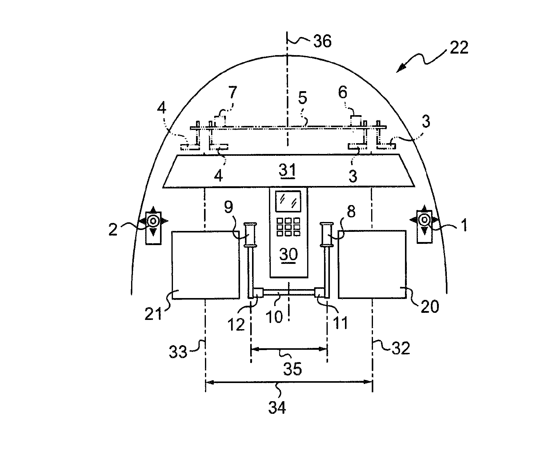
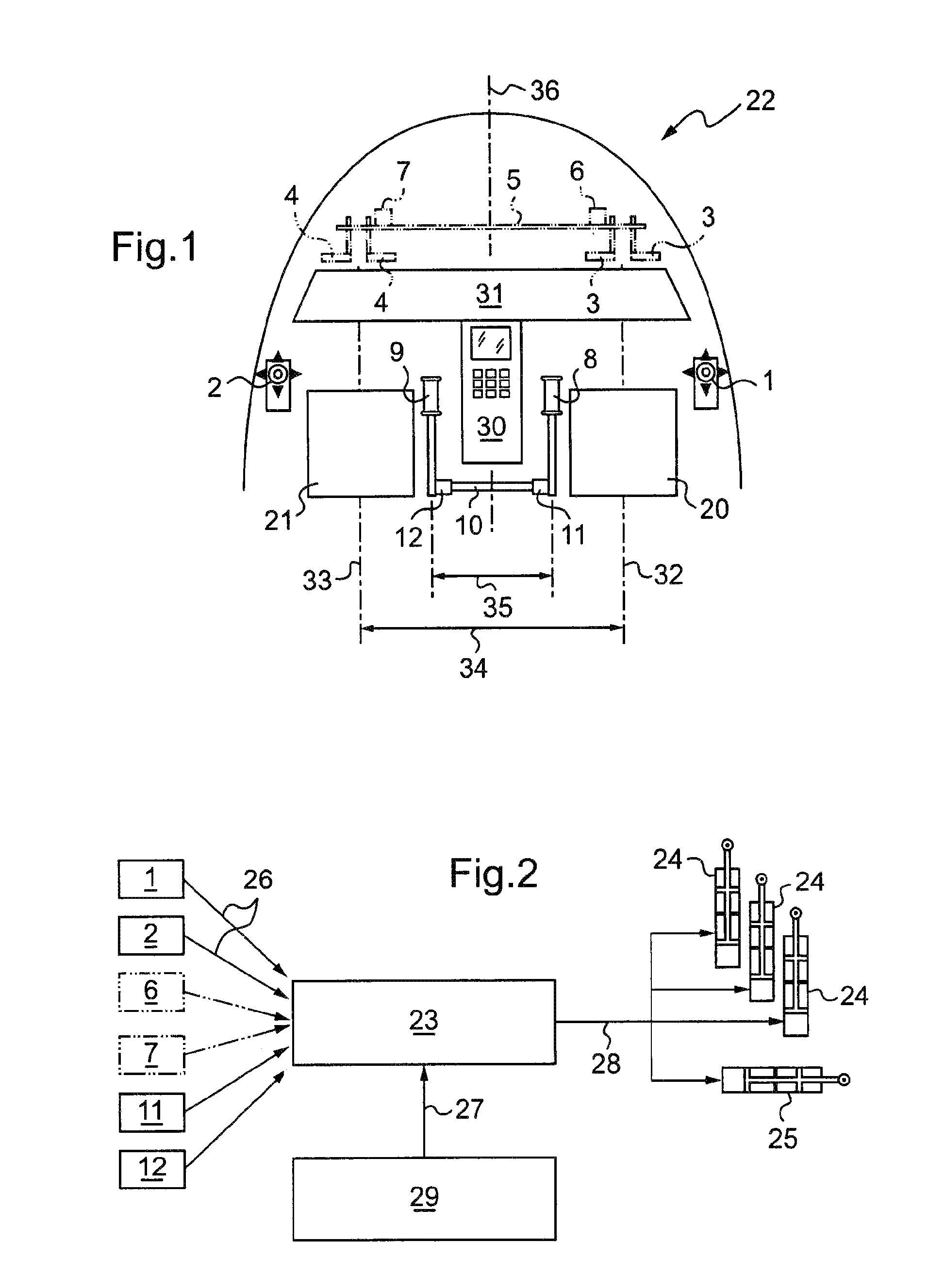
[0033]In an embodiment, the invention applies to a helicopter having a cockpit 22 of the side-by-side type, and provided with an electric fly-by-wire (FBW) control system with side sticks 1 and 2 for controlling roll and pitch, as shown in FIG. 1. The connections between the computers, the state sensors, and the servo-controls of the FBW control system are shown in FIG. 2.

[0034]With reference to FIG. 1 in particular, the cockpit 22 of the rotorcraft presents general symmetry about a fore-and-aft vertical plane whose trace in the plane of FIG. 1 is referenced 36.

[0035]The cockpit 22 has two seats 20, 21 facing an instrument panel 31 disposed transversely across the longitudinal axis 36 of the rotorcraft; the instrument panel carries the usual instruments and is associated with a console 30 that extends in part between the seats 20 and 21, and in part in front of the seats.

[0036]The distance 34 between the respective fore-and-aft axes 32 and 33 of the seats 20 and 21 (referred to as t...


PUM


Abstract

The invention relates to a rotorcraft cockpit having a left seat and a right seat placed side-by-side, a console extending between the seats, two side sticks, one situated to the right of the right seat and the other situated to the left of the left seat, enabling the pilot to control roll and pitch; a flight control system comprising sensors associated with the side sticks and a computer connected to the sensors serves to convert the orders applied by the pilot to the side sticks into signals for controlling actuators in order to vary roll and pitch; a piloting relationship integrated in the computer stabilizes the response of the rotorcraft in roll and in pitch when a side stick is actuated, and maintains the attitudes in roll and pitch at reference values when neither side stick is actuated.

Description

[0001]The present invention relates to a flying control device for a rotorcraft and to rotorcraft including the device.FIELD OF THE INVENTION[0002]The technical field of the invention is that of helicopter manufacture.[0003]The present invention relates to a flight control system for a rotary wing aircraft, and in particular to the disposition of control members in the cockpit. The configuration proposed serves to improve the man / machine interface when using side sticks controllers for controlling roll and pitch.BACKGROUND OF THE INVENTION[0004]Helicopters are generally designed so that the pilot controls roll and pitch with the right hand via a cyclic pitch stick, and the vertical axis with the left hand via a collective pitch control lever. Until now, helicopters and tilt-rotor aircraft with a side-by-side cockpit have used this configuration for the control members.[0005]In a side-by-side cockpit with side sticks, this configuration raises a major problem in terms of the ergonomy...

Claims


Application Information

Patent Timeline
Patent Type & Authority Patents(United States)
IPC IPC(8): B64C13/12
CPCB64C13/12B64C27/56B64D43/00G05G13/00Y02T50/44Y02T50/40
Inventor ROLLET, PHILIPPE
Owner EUROCOPTER
Why Eureka
Try Eureka