On-vehicle rotary electric machine operating on two modes of rectification

a rotary electric machine and rectification technology, applied in the direction of locomotive transmission, electric generator control, motor propulsion transmission, etc., can solve the problems of insufficient torque at the revolution speed, inability to send electric current from the battery during motor operation, unstable engine rotation, etc., to achieve the effect of high output and equivalent reduction of inductan

Active Publication Date: 2011-11-08
DENSO CORP
View PDF23 Cites 7 Cited by
  • Summary
  • Abstract
  • Description
  • Claims
  • Application Information

AI Technical Summary

Benefits of technology

[0015]The present invention has been achieved in light of the above-described issues. An object of the present invention is to provide a vehicle rotary electric machine that can enable size reduction, high output, and high efficiency during power generation and high torque during motor-driving at a low cost.
[0017]When the multi-phase winding is connected by Y-connection, an electrical current always flows to two phases when ordinary rectification is performed. The inductance becomes a geometric sum. In the present invention, the neutral point rectification mode is provided in which rectification is performed through use of a switch corresponding to the neutral point on an electric potential side differing from the high-side (i.e., higher electrical potential side) and low-side (i.e., lower electrical potential side) winding end switching elements. Therefore, in the neutral point rectification mode, the electrical current enters and exits from the neutral point, and only flows through the winding of one phase. Therefore, the inductance is only that of a winding of a single phase. In other words, a low-inductance winding can be achieved. In the present invention, the control device can arbitrarily switch between two control modes. As a result, the control device can change the inductance using the same three-phase winding. Therefore, only a single set of three-phase windings is required. Size reduction, high output, and high efficiency can be obtained during power generation and high torque can be actualized during motor-driving (motor operation) at a low cost. Because characteristics can be arbitrarily changed by the control mode being switched, optimal power generation characteristics or motor torque characteristics can be achieved at any given time.
[0018]The above-described control device switches between the multi-phase full-wave rectification mode and the neutral point rectification mode depending on a revolution speed of the rotor. As a result of the control mode being switched depending on the revolution speed, a control program can be simplified. In addition, because the power generation characteristics and the motor torque characteristics are dependent on the revolution speed, more favorable characteristics can be achieved.
[0019]The above-described control device switches to the multi-phase full-wave rectification mode when the revolution speed is slower than a predetermined revolution speed and to the neutral point rectification mode when the revolution speed is faster than the predetermined revolution speed. As a result, during power generation, inductance of the stator can be increased to enhance power generating capability when the revolution speed is slower than the predetermined revolution speed. On the other hand, when the revolution speed is faster than the predetermined revolution speed, the inductance can be reduced. Reaction can be reduced and a high output can be achieved. During motor-driving, a high torque can be achieved to reduce the inductance when the revolution speed is faster than the predetermined revolution speed.
[0021]The above-described rectification control device switches to the multi-phase full-wave rectification mode when operation is performed as the generator and to the neutral point rectification mode when operation is performed as the motor. As a result, during power generation, a high output can be achieved even at a low-speed revolution. During motor-driving, the inductance can be equivalently reduced. Therefore, simultaneous power generation and motor-driving, which was difficult in a vehicle generator, can be obtained.

Problems solved by technology

Thus, the generator is required to be motor-driven while the engine rotation can become unstable due to unexpected disturbance of torque of the engine.
Therefore, electric current cannot be sent from the battery during motor operation.
Hence, a sufficient torque cannot be generated at the revolution speed.
Although some torque can be extracted through weakening current-flowing in the field winding of the generator, the torque is not sufficient for the purpose described above.
In a vehicle rotary machine having both power generation and engine driving functions, it is difficult to actualize the characteristics required during power generation and the characteristics required for torque of the engine with the same inductance.
A conflicting request is made in that, when the power generation characteristics are given priority, motor characteristics become a state in which the drive torque is insufficient.
When the motor characteristics are given priority, the power generation output during idle rotation becomes insufficient.
Problems occur in that a configuration of the stator becomes complicated and cost rises.
For example, compared to six rectifying elements ordinarily required, nine switching elements are additionally required, thereby also contributing to the increase in cost.
In addition, the rotary electric device disclosed in Japanese Patent Laid-open Publication No. 2007-99066 is a technology used only during motor-driving and in response to an abnormal situation, and does not meet the above-described requirements.
Problems occur such as the rotation not being smooth.

Method used


Image

  • On-vehicle rotary electric machine operating on two modes of rectification
  • On-vehicle rotary electric machine operating on two modes of rectification
  • On-vehicle rotary electric machine operating on two modes of rectification

Examples


Embodiment Construction

[0032]A vehicle rotary electric machine according to an embodiment to which the present invention is applied will be described in detail with reference to the drawings FIGS. 3 to 9.

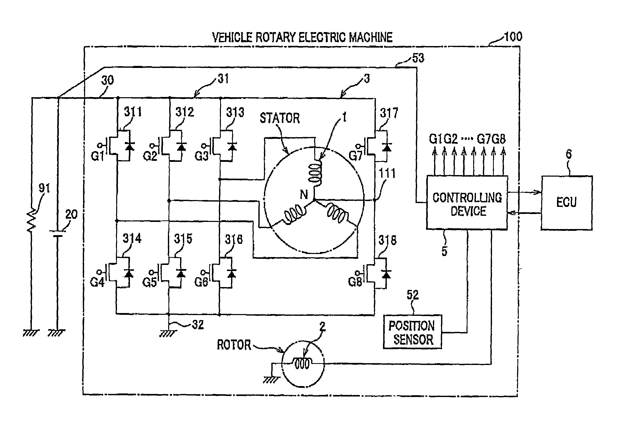
[0033]FIG. 3 is a connection wiring diagram showing an overall configuration of a vehicle rotary electric machine according to an embodiment. As shown in FIG. 3, the rotary electric machine 100 according to the present embodiment includes a three-phase winding 1, a field winding 2, a rectifying device 3, and a controlling device S. The three-phase winding 1 serves as a multi-phase winding included in a stator. The field winding 2 is included in a rotor. The three-phase winding 1 is wound around a stator core (not shown) at a pitch of 180 electrical degrees equivalent to an amount for a single magnetic pole of the rotor in which the field winding 2 is provided. Each phase winding is connected by a Y-connection. Three output terminals (winding terminals) of each phase of the three-phase winding 1 and a neut...


PUM


Abstract

A rotary electric machine for a vehicle includes a rotor, a stator and a rectifying device for current AC / DC conversion. The machine operates as a motor and a generator. The machine includes a multi-phase windings, switching elements forming a rectifying device, and a controller for controlling a current path of the multi-phase windings by switching the switching elements on and off to perform two modes of operation. The switching elements are switched such that one end of each windings is connected to either a high electrical potential end or a low electrical potential end of the rectifying device and the other ends of the windings connected together to be the same electrical potential are connected to either the high electrical potential end or the low electrical potential end in the rectifying device.

Description

CROSS-REFERENCE TO RELATED APPLICATION[0001]This application is related to Japanese Patent Application NO. 2007-225748 filed on Aug. 31, 2007, the contents of which are hereby incorporated by reference.BACKGROUND OF THE INVENTION[0002]1. Field of the Invention[0003]The present invention relates to a rotary electric machine mounted on a vehicle, and in particular, to the rotary electric machine having a rotor and a stator equipped with multi-phase windings for making the machine function as a motor and a generator.[0004]2. Description of the Related Art[0005]In recent years, some vehicles have a function for stopping the idle rotation (i.e., idling) of the engine for saving consumption of fuel. In such vehicles, the engine is frequently turned off every time and started up every time the vehicle stops. Because the stop and start-up of the engine is repeated, it is desired that a generator mounted on the vehicle be motor-driven and serves as a starter which has a problem regarding the...

Claims


Application Information

Patent Timeline
Patent Type & Authority Patents(United States)
IPC IPC(8): H02P9/00H02K23/52
CPCH02P9/48H02P27/06H02P2101/45H02P2209/01
Inventor UMEDA, ATSUSHIINOKUCHI, TAKATOSHI
Owner DENSO CORP
Why Eureka
Try Eureka