Supercharge Your Innovation With Domain-Expert AI Agents!

Control device and control method

a control device and control method technology, applied in the direction of motor/generator/converter stopper, dynamo-electric converter control, instruments, etc., can solve the problems of affecting the accuracy of control device, so as to improve the accuracy of detection of the speed of the driven body and stably control the drive

Active Publication Date: 2011-11-15
SHARP KK
View PDF12 Cites 3 Cited by
  • Summary
  • Abstract
  • Description
  • Claims
  • Application Information

AI Technical Summary

Benefits of technology

The invention provides a control device and method for accurately detecting the speed of a driven body and controlling the drive means in a way that ensures stability and control. The control device includes a periodic signal acquisition system that detects the pulse signal that corresponds to the speed of the driven body, an edge detection system that detects the rising or falling edge of the pulse signal, a timer system that starts timekeeping at the time of edge detection, a computing system that calculates the period of the pulse signal between the detected edges, a storing system that stores the calculated period, and a comparing system that compares the measured time with the stored period to determine the speed of the driven body. The control device can output either the measured time or the stored period, depending on the comparison result. This invention provides a more accurate and stable control device for driving the driven body.

Problems solved by technology

However, an actual speed may not be zero and in such a case, there is a problem of unstable servo control such that the speed may be so high for the recording sheet to be fed over the target position.
The unstable servo control impedes the recording sheet from being printed at desired position, and problems are caused, for example, that in the case where the recording sheet fails to stop at the target position and stops over the target position, a gap will appear between print data, while in the case where the recording sheet stops before the target position, the print data will overlap each other.
Moreover, in the case where the recording sheet has reached far over the target position, the recording sheet will need to be moved in the opposite direction and back to the target position, resulting in lower print speed.
Further, in the case where the speed information is controlled so as not to be zero when the position information is not updated, the speed information will not be zero even when the actual speed is zero, therefore causing a problem of unstable servo control as described above.

Method used


Image

  • Control device and control method
  • Control device and control method
  • Control device and control method

Examples


first embodiment

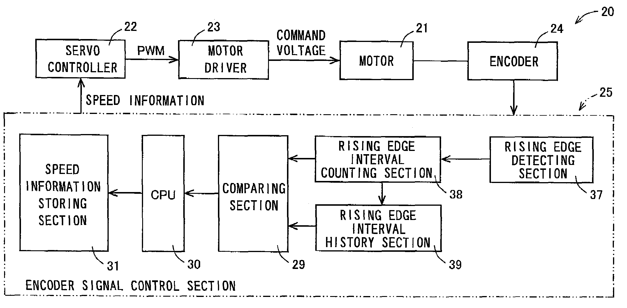
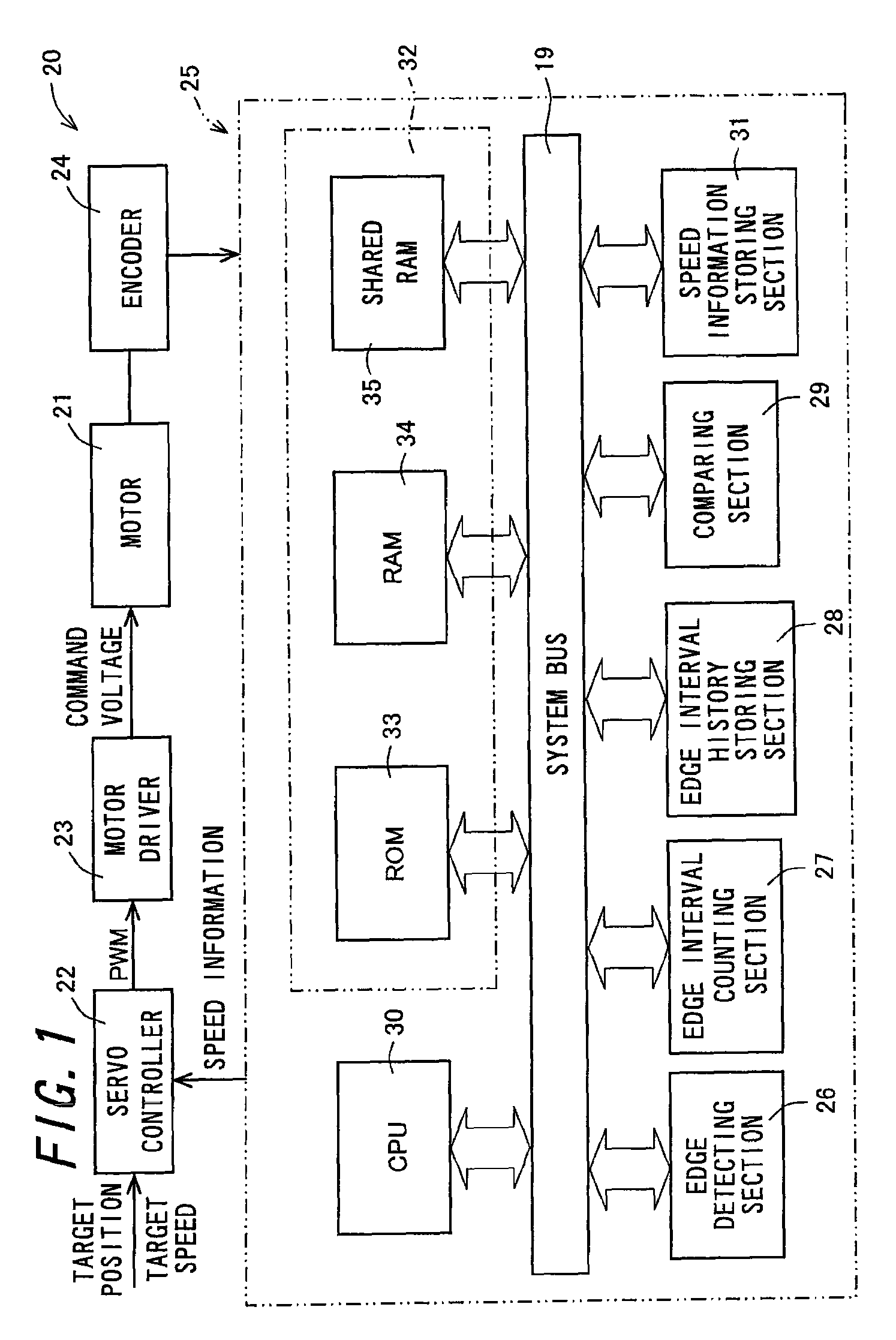
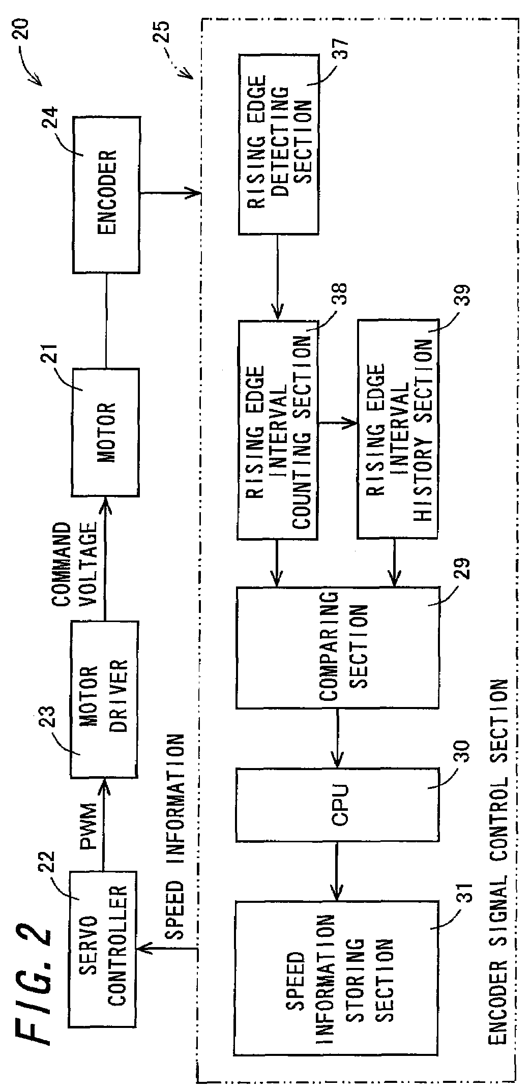
[0198]FIG. 1 is a block diagram schematically showing an electrical configuration of a servo control system 20 according to the invention. The servo control system 20 performs a servo control on drive means such as a motor 21 by feeding back speed information of a driven body being displaced by the drive means.

[0199]The servo control system 20 is a device for controlling the drive means driving the driven body. The drive means is realized by a drive source such as the motor 21. The drive means is mounted in an inkjet apparatus, for example, and if it is an automatic sheet feeder (ASF) motor which feeds a recording medium to a print position, the driven body corresponds to the recording medium. Accordingly, the servo control system 20 controls the ASF motor so that the recording medium can be brought to a desired print position with high accuracy. The servo control system 20 includes a servo controller 22, a motor driver 23, a motor 21, an encoder 24, and an encoder signal control se...

sixth embodiment

[0355]Consequently, the encoder signal control section 25e of the present embodiment can achieve the same operation and effect as those of the above-described encoder signal control section 25d of the

[0356]Next, a servo control system 20d according to an eighth embodiment of the invention will be explained. The servo control system 20d of the present embodiment has a similar configuration to those of the above-described servo control system 20d of the fifth and sixth embodiments, with the encoder signal control section 25d operating differently, and the operation of the encoder signal control section 25d will be therefore explained.

[0357]The comparing section 29 has functions of the first to fourth comparing means and compares lengths of time between the above-described first to fourth total time-length and the above-described total period lengths, respectively, and then gives the comparison results to the CPU 30.

[0358]During the first comparison term from when the falling edge of t...


PUM


Abstract

The invention relates to a control device and a control method which enhance accuracy in detecting a speed of a driven body to stably control drive means. An encoder signal control section (25) compares lengths of time between a rising measurement time kept by a rising edge interval counting section (38) and a rising period of the latest rising edge stored in a rising edge interval history section (39), and then outputs a value of either the rising measurement time or the rising period, whichever is longer based on a comparison result, so that a period of a pulse signal (36) can be accurately predicted and be a real-time approximate, which allows for accurate calculation of the speed of the driven body based on the accurately outputted period of the pulse signal (36), and the accuracy in detecting the speed of the driven body can be enhanced with the result that the drive means can be stably controlled.

Description

TECHNICAL FIELD[0001]The invention relates to a control device and control method of controlling drive means such as a motor.BACKGROUND ART[0002]An inkjet recording apparatus of conventional art is mounted in a printer, a facsimile machine, and a copier, and used as recording means which records an image onto a recording medium in the form of a paper sheet or a thin plastic sheet on the basis of image information. Such an inkjet recording apparatus conducts recording with a print head ejecting ink droplets and therefore has features that the recording means can be easily downsized, that dense images can be recorded at high speed, that the running cost is low, and that the level of noise generated thereby is low owing to the non-impact system. Moreover, the inkjet apparatus has also an advantage that color images are easily recorded with use of multicolor ink.[0003]Drive sources of the inkjet recording apparatus include, for example, a carriage motor which reciprocates and drives a c...

Claims


Application Information

Patent Timeline
Patent Type & Authority Patents(United States)
IPC IPC(8): H02P7/06G01D5/244
CPCB41J19/202G01D5/246G01P3/481H02P6/16
Inventor ISHIKAWA, KAZUTOSHI
Owner SHARP KK
Features
  • R&D
  • Intellectual Property
  • Life Sciences
  • Materials
  • Tech Scout
  • Unparalleled Data Quality
  • Higher Quality Content
  • 60% Fewer Hallucinations
Learn More