Physical layer repeater configuration for increasing MIMO performance

a repeater and physical layer technology, applied in the field of wireless communication, can solve the problems of lack of performance, rarely realized performance levels, and spontaneous generation and transmission of wireless network nodes, and cannot be temporally predictabl

Inactive Publication Date: 2011-11-15
QUALCOMM INC
View PDF343 Cites 27 Cited by
  • Summary
  • Abstract
  • Description
  • Claims
  • Application Information

AI Technical Summary

Problems solved by technology

While the specifications of products utilizing the above standard wireless protocols commonly indicate data rates on the order of, for example, 54 MBPS and ranges on the order of, for example, 100 meters, these performance levels are rarely, if ever, realized.
This lack of performance is due to attenuation of the radiation paths of RF signals, which are typically in the range of 2.4 GHz, in an indoor environment.
One significant complication is that the system receivers and transmitters operate at the same frequency for a WLAN utilizing an 802.11 or an 802.16 WMAN wireless protocol.
The packets from each wireless network node are spontaneously generated and transmitted and are not temporally predictable.
In the case where the receive and transmit times are known, synchronization of the timing can be problematic and can drive up the expense of the product.
While existing CDMA systems employ directional antennas and physical separation of the receive and transmit antennas to achieve this isolation, such techniques are not practical for WLAN repeaters in many operating environments such as in the home where lengthy cabling is not desirable or may be too costly.
However, in a typical home WLAN environment, multi-path transmission capability and spatial diversity are limited for many of the same reasons discussed above in connection with lack of performance of wireless products in a home or indoor environment.

Method used


Image

  • Physical layer repeater configuration for increasing MIMO performance
  • Physical layer repeater configuration for increasing MIMO performance
  • Physical layer repeater configuration for increasing MIMO performance

Examples


Embodiment Construction

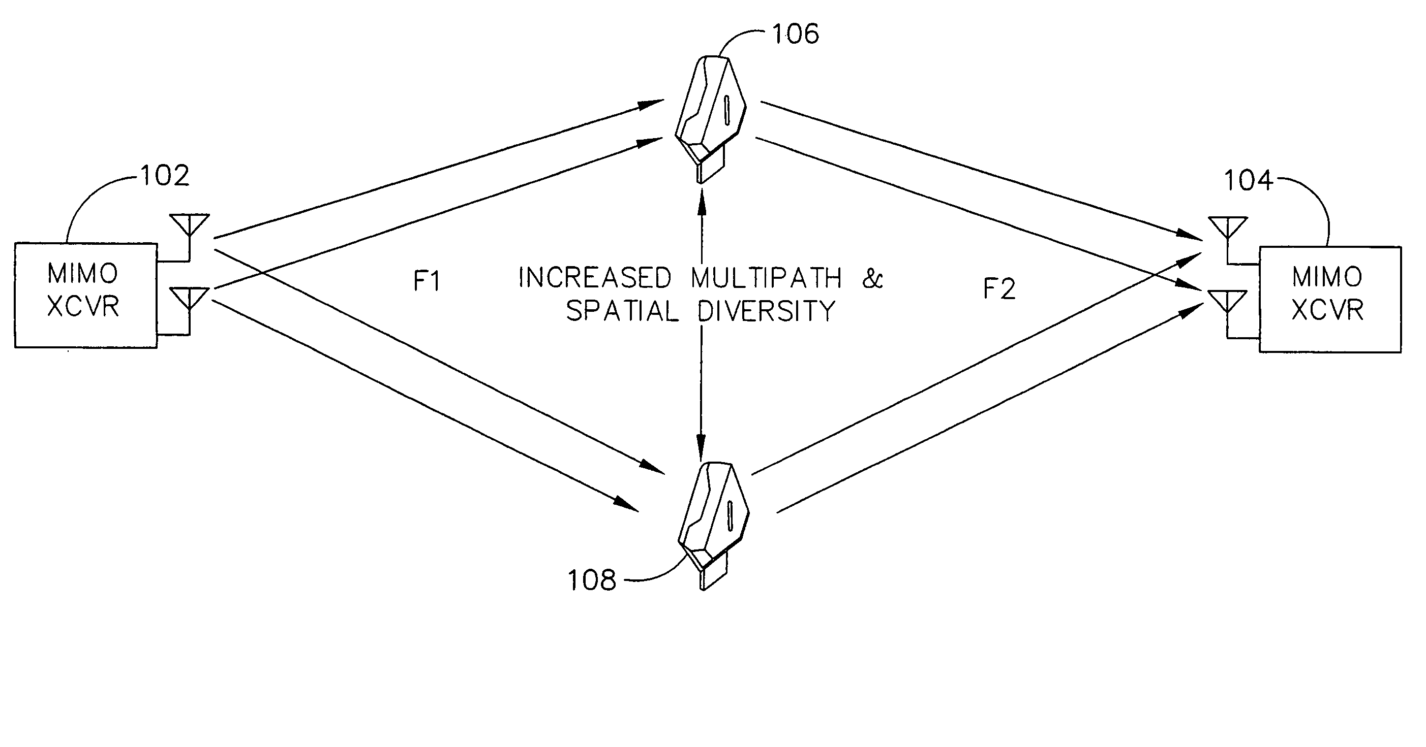
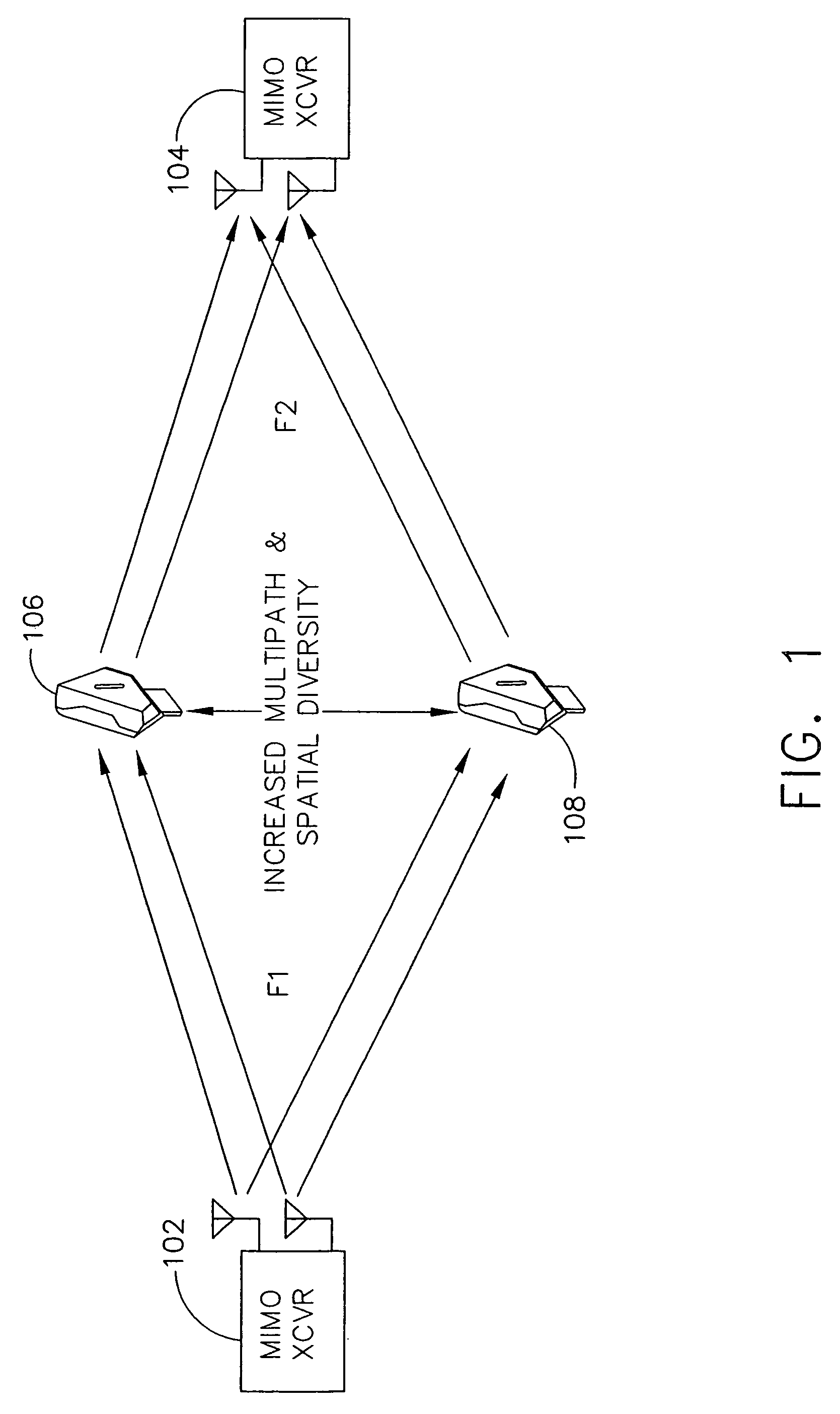
FIG. 1 illustrates a multi-input, multi-output (MIMO) protocol-based network (network) 100, such as is described in IEEE 802.11 draft proposals from TGnSync and WWise consortiums (the contents of which are hereby incorporated by reference) that enables consistent independent signal paths to be generated even in environments, such as home environments, in which multi-path transmission capability and spatial diversity are typically limited. MIMO transceivers 102, 104, hereinafter referred to as network stations, may be any type of wireless communications devices including client devices, MIMO-enabled access points, or any other type of known network node capable of operating in MIMO mode and of transmitting and / or receiving data in a wireless environment based on a wireless protocol such as 802.11b, 802.11g, or 802.11n (proposed), in the network 100. The network stations 102, 104 are capable of communicating with one another over distances outside of normal coverage ranges through wir...


PUM


Abstract

A wireless network includes at least one Multiple Input Multiple Output (MIMO) wireless network station and two or more physical layer repeaters. Each of the physical layer repeaters is for receiving a wireless signal to or from the at least one MIMO wireless network station and re-transmitting the wireless signal while continuing to receive the wireless signal. The repeaters may be either frequency translating repeaters or non-frequency translating repeaters.

Description

FIELD OF THE INVENTIONThe present invention relates generally to wireless communications and more specifically to a repeater configuration for increasing the coverage of wireless networks.BACKGROUND OF THE INVENTIONSeveral standard protocols for wireless local area networks, commonly referred to as WLANs, are becoming popular. These include protocols such as 802.11 (as set forth in the 802.11 wireless standards), Wi-MAX, and Bluetooth. The standard wireless protocol with the most commercial success to date is the 802.11g protocol.While the specifications of products utilizing the above standard wireless protocols commonly indicate data rates on the order of, for example, 54 MBPS and ranges on the order of, for example, 100 meters, these performance levels are rarely, if ever, realized. This lack of performance is due to attenuation of the radiation paths of RF signals, which are typically in the range of 2.4 GHz, in an indoor environment. Base to receiver ranges are generally less t...

Claims


Application Information

Patent Timeline
Patent Type & Authority Patents(United States)
IPC IPC(8): H04L27/28
CPCH04B7/022H04B7/2606H04L25/24H04L2027/0044
Inventor PROCTOR, JR., JAMES A.GAINEY, KENNETH M.OTTO, JAMES C.
Owner QUALCOMM INC
Why Eureka
Try Eureka