Working machine and emergency lowering system

a technology of working machine and emergency lowering system, which is applied in the field of working machine, can solve the problems of much more expensive realization of electronic activation

Active Publication Date: 2011-11-22
LEIBHERR HYDRAULIKBAGGER GMBH
View PDF20 Cites 3 Cited by
  • Summary
  • Abstract
  • Description
  • Claims
  • Application Information

AI Technical Summary

Benefits of technology

[0006]Therefore, it is the object of the present invention to provide a safer emergency lowering system for such working machine.
[0007]In accordance with the invention, this object is solved by a working machine according to the description herein. The working machine of the invention, in particular a traveling material-handling machine, in particular a hydraulic excavator, comprises a basic machine, a cabin and a cabin arm pivotally mounted on the basic machine, by means of which the position of the cabin with respect to the basic machine can be varied. The cabin arm can be swivelled with respect to the basic machine about a horizontal axis by means of at least one hydraulic actuator, wherein the cabin is pivotally mounted on the cabin arm via a hydraulic inclination adjustment device. In accordance with the invention, the working machine now includes an emergency lowering system for the cabin, in which an inclination emergency valve is provided for the inclination adjustment device of the cabin, which in a case of emergency lowering provides for an alignment of the cabin into a normal position. In this way, it is ensured that in a case of emergency lowering the cabin is moved into the normal position, in which the cabin floor is aligned substantially horizontally, so that in a case of emergency lowering the cabin arm and the cabin there is no risk of injury for the operator due to an unintentional inclination of the cabin out of the normal position.
[0009]In accordance with the invention, the inclination emergency valve for the inclination adjustment device advantageously is controlled hydraulically via the pressure in the emergency drain line of the hydraulic actuator of the cabin arm. This provides for a both safe and reliable activation of the inclination emergency valve. The inclination emergency valve automatically provides for an alignment of the cabin into a normal position, when emergency lowering of the cabin arm is activated, without the operator having to separately activate the inclination emergency valve for this purpose. In particular, there is no need for a separate emergency drain cock for the inclination adjustment device. In addition, the activation of the inclination emergency valve via the pressure in the emergency drain line also allows an alignment of the cabin into the normal position when a tube of the emergency drain line bursts and an unintentional emergency lowering is activated thereby. The hydraulic activation allows a both safe and simple construction, whereas an electronic activation would be much more costly to realize.
[0010]Advantageously, the emergency drain line and / or the control input of the inclination emergency valve is connected with a hydraulic accumulator. Advantageously, the same is charged when lifting the cabin and is drained in a case of emergency lowering. In this way, it is ensured that in a case of emergency lowering the inclination emergency valve is not activated too fast, and thus ensures a controlled movement of the cabin.
[0011]In accordance with the invention, the cabin advantageously is pivotally mounted on a pivot point arranged above its center of gravity, so as to hang on the cabin arm, wherein the inclination emergency valve enables the inclination adjustment of the cabin with respect to the cabin arm in a case of emergency lowering, so that the cabin is aligned in its normal position by gravity. In a case of emergency lowering, the emergency inclination valve of the invention thus merely ensures that the inclination adjustment device no longer determines the alignment of the cabin with respect to the cabin arm, but the cabin can substantially freely swing about its pivot point. When the cabin arm now is lowered in a case of emergency lowering, the cabin can freely rotate with respect to its attachment on the cabin arm and thus remains in its normal position. Advantageously, an attenuation of the pendular movement of the cabin is provided here, so that the cabin will safely swing back into the normal position, when it is in an inclined position upon activation of emergency lowering.
[0012]Advantageously, the inclination emergency valve of the invention comprises a shutoff valve, which is arranged in the hydraulic circuit of the inclination adjustment device between supply line and discharge line of the inclination adjustment deivce and connects the same with each other in a case of emergency lowering. The shutoff valve thus can ensure freewheeling of the inclination adjustment device and hence enables the movement of the cabin with respect to the cabin arm. On the other hand, if there is no case of emergency lowering, the shutoff valve will close, so that the alignment of the cabin with respect to the cabin arm can be adjusted by a corresponding pressurization of the inclination adjustment device, e.g. via a hydraulic pump.

Problems solved by technology

The hydraulic activation allows a both safe and simple construction, whereas an electronic activation would be much more costly to realize.

Method used


Image

  • Working machine and emergency lowering system
  • Working machine and emergency lowering system
  • Working machine and emergency lowering system

Examples


Embodiment Construction

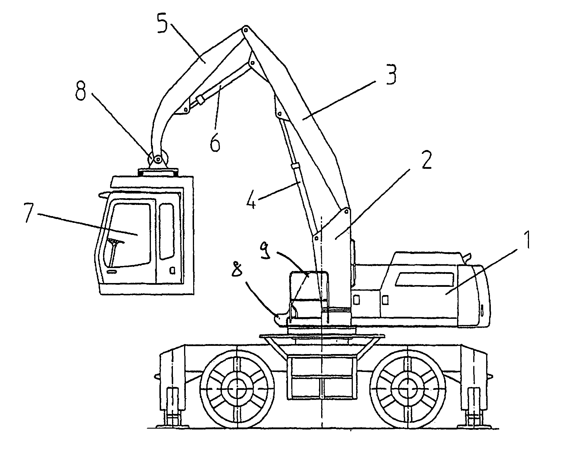
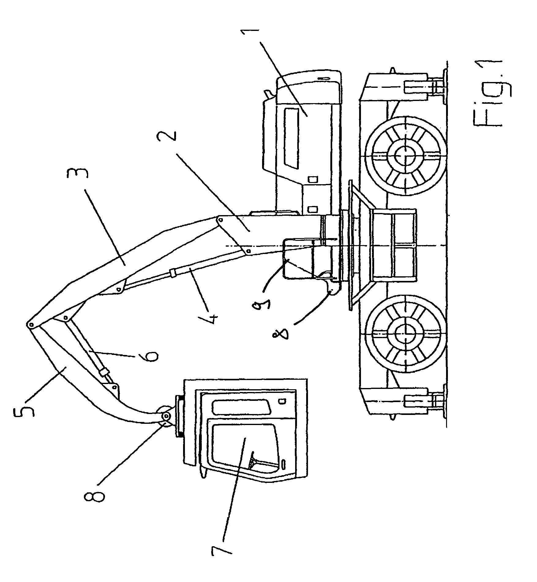
[0021]FIG. 1 now shows an embodiment of the working machine in accordance with the invention. The same includes a traveling undercarriage with an uppercarriage 1 rotatably mounted on the undercarriage about a vertical axis of rotation, which together form the basic machine. On this basic machine, a working boom not shown in FIG. 1 usually is pivotally mounted, which includes a working tool such as a bucket, a grab or a hook, wherein the working boom can be used e.g. for material handling. In the embodiment shown in FIG. 1, the working boom not shown in the drawing would be pivotally mounted on the pivot points 8 and 9 on the uppercarriage 1. The working machine can be a material-handling machine for instance for wood, scrap or any other goods, a crane or an excavator, in particular a hydraulic excavator.

[0022]The working machine includes a cabin 7, from which the working machine is operated by an operator. The cabin 7 is arranged on the basic machine via a cabin arm, wherein the cab...


PUM


Abstract

The present invention relates to a working machine, in particular a traveling material-handling machine, in particular a hydraulic excavator, comprising a basic machine, a cabin and a cabin arm pivotally mounted on the basic machine, by means of which the position of the cabin with respect to the basic machine can be varied, wherein the cabin arm can be swivelled with respect to the basic machine about a horizontal axis by means of at least one hydraulic actuator, and wherein the cabin is pivotally mounted on the cabin arm via a hydraulic inclination adjustment device. In accordance with the invention, the cabin includes an emergency lowering system, in which an inclination emergency valve is provided for the inclination adjustment device of the cabin, which in a case of emergency lowering provides for alignment of the cabin into a normal position.

Description

BACKGROUND OF THE INVENTION[0001]The present invention relates to a working machine, in particular a traveling material-handling machine, in particular a hydraulic excavator, comprising a basic machine, a cabin and a cabin arm pivotally mounted on the basic machine, by means of which the position of the cabin with respect to the basic machine can be varied, wherein the cabin arm can be swivelled with respect to the basic machine about a horizontal axis by means of at least one hydraulic actuator, and wherein the cabin is pivotally mounted on the cabin arm via a hydraulic inclination adjustment device.[0002]Such working machine is known from DE 20 2004 019 708 U1.[0003]In such working machines, it is possible to vary the position of the cabins with respect to the basic machine by means of the cabin arm, so that an operator always has an optimum view of the working area and / or the tool of the working machine. When the cabin arm is swivelled, the cabin would be inclined with respect to...

Claims


Application Information

Patent Timeline
Patent Type & Authority Patents(United States)
IPC IPC(8): B66C13/54B62D33/067E02F9/16
CPCB62D33/0617B62D33/063B66C13/54E02F9/166E02F9/2217E02F9/226
Inventor MEIER, SIMON
Owner LEIBHERR HYDRAULIKBAGGER GMBH
Why Eureka
Try Eureka