
Inertial positioner and an optical instrument for precise positioning

a technology of optical instruments and precision positioning, applied in the direction of engine lubrication, liquid/fluent solid measurement, and manufacture/assembly of piezoelectric/electrostrictive devices, can solve the problems of difficult assembly, difficult manufacturing, and insufficient rigidity of assembly for many applications, so as to achieve precise positioning of objects and accurate determination of object position

Inactive Publication Date: 2011-11-22
PRYADKIN DR SERGIY
View PDF17 Cites 9 Cited by
  • Summary
  • Abstract
  • Description
  • Claims
  • Application Information

AI Technical Summary

Benefits of technology

The solution provides a compact, rigid, and cost-efficient 3D positioning system capable of achieving mechanical resonant frequencies above 10 kHz, suitable for scanning probe microscopy and nano-lithography, enabling precise atomic resolution and robustness against mechanical vibrations.

Problems solved by technology

Another embodiment of Pan's invention provides simultaneous motion in two dimensions, but such motion is not independent along Cartesian axes and makes the readout of coordinates difficult.
The preferred embodiment of this invention allows a compact multi-axis positioning assembly, but such assembly is not rigid enough for many applications, for example, its low mechanical resonant frequency limits its use in scanning probe microscopy.
The resulting setup is quite complex and difficult to manufacture, as it requires a complicated alignment.

Method used


Image

  • Inertial positioner and an optical instrument for precise positioning
  • Inertial positioner and an optical instrument for precise positioning
  • Inertial positioner and an optical instrument for precise positioning

Examples


Embodiment Construction

[0044]We now turn to the detailed description of this invention.

I. An Inertial Positioner

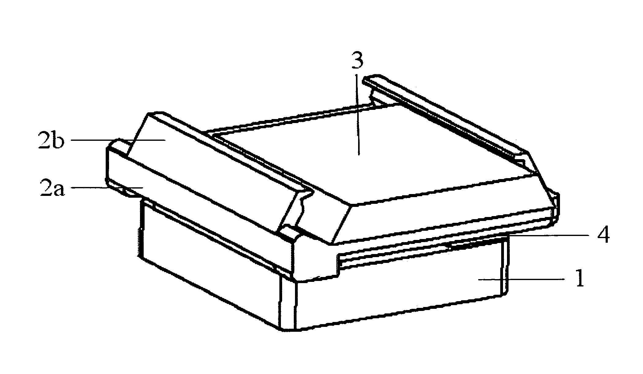
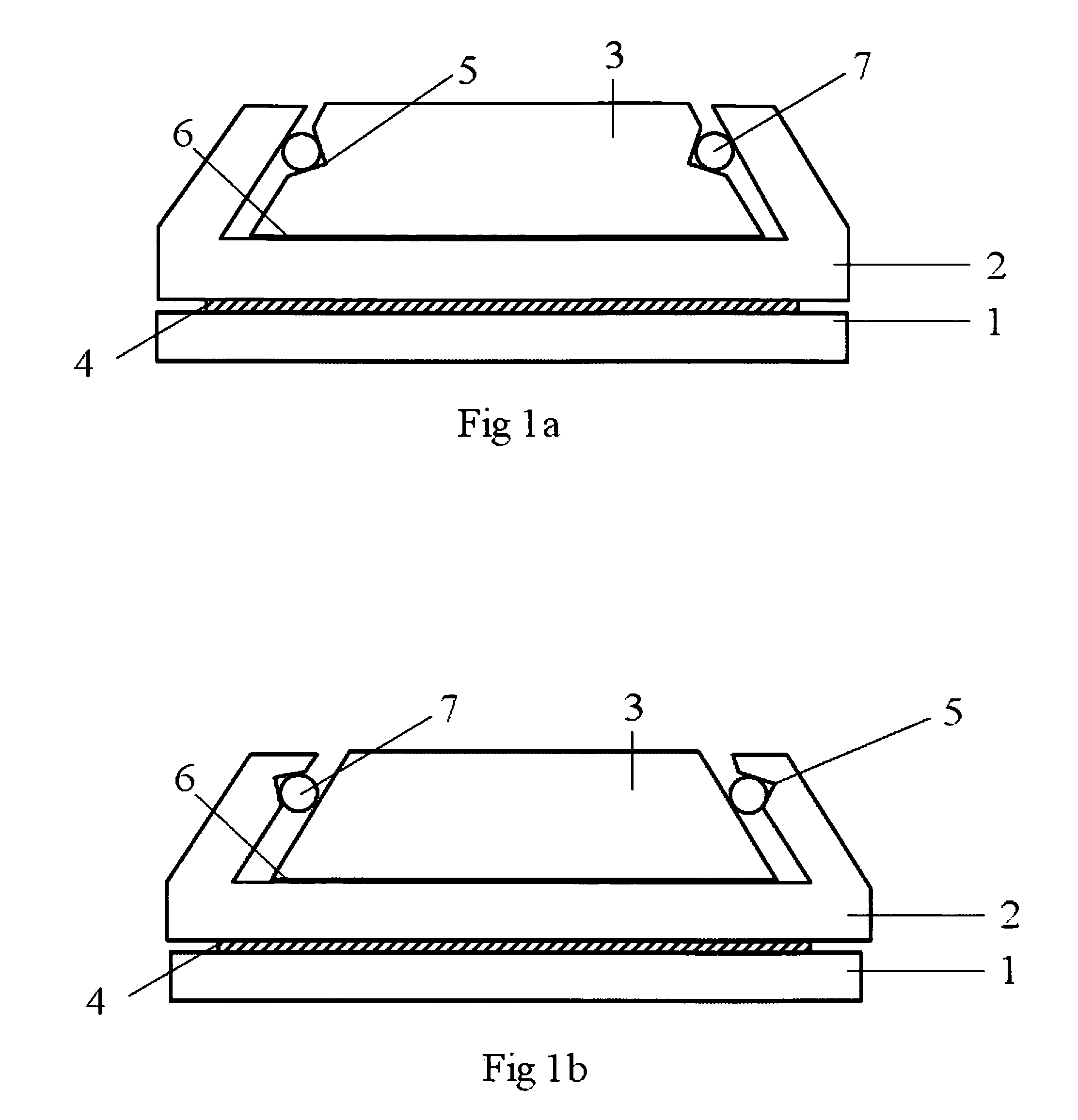
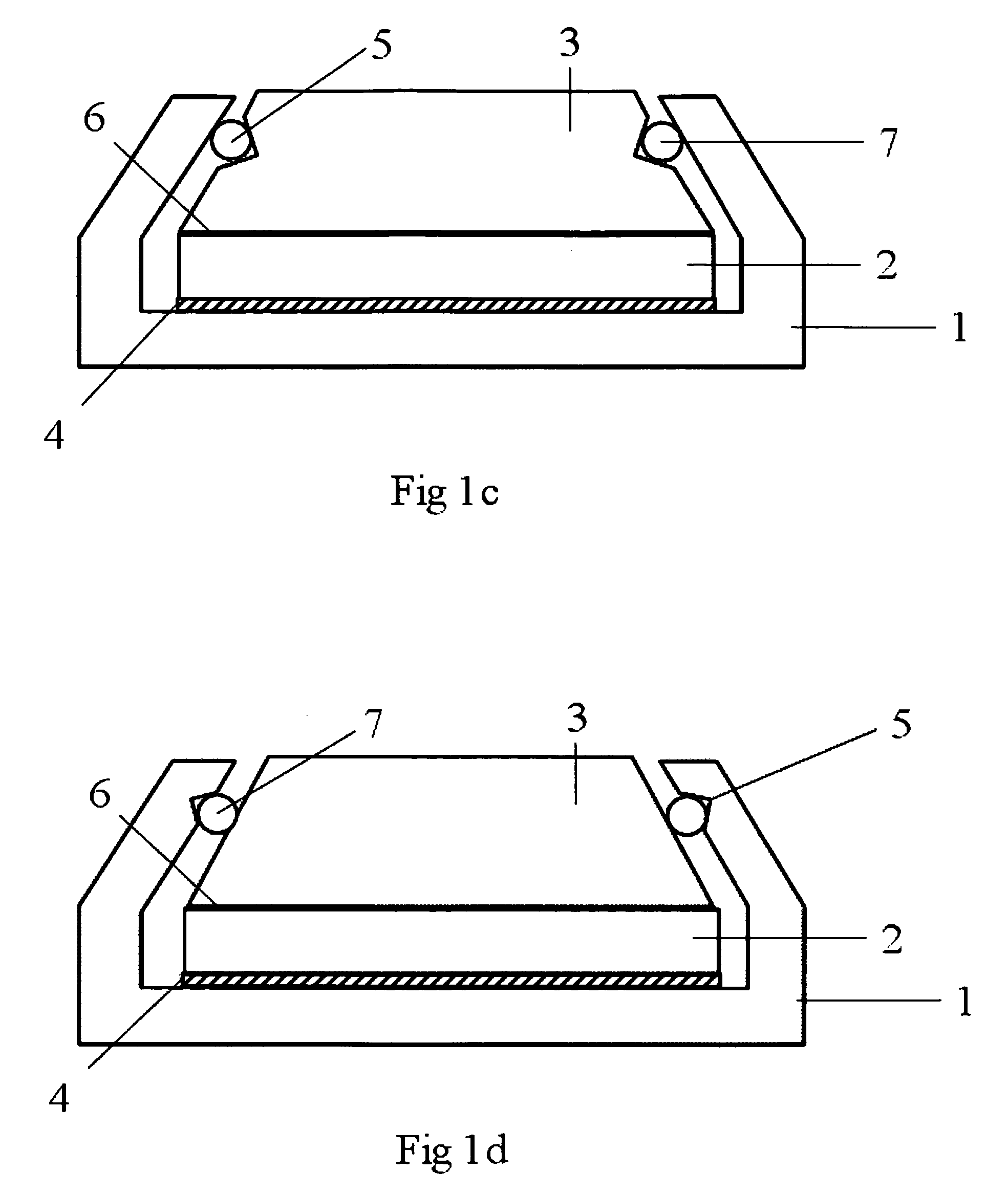
[0045]In FIG. 1a through FIG. 4a series of embodiments of a single-axis inertial positioner is presented. Turning to FIG. 1a, the represented positioner is an essentially rigid construction comprising a frame having as frame elements: a base 1, a carrier 2, and an inertial actuator 4 which is disposed on base 1 of the positioner; further comprising a movable platform 3 to which an object to be positioned is affixed. Base 1 may be a platform of another positioner, or any other suitable rigid object. One surface of the actuator is bonded to the base, while the other surface is bonded to the carrying element. In this invention, a preferred embodiment of an inertial actuator 4 is a piezo-electric actuator, more preferably a stack of piezo-electric elements. Less preferred embodiments of an inertial positioner comprise a magnetostrictive or an electromagnetic actuator.

[0046]The piezo-electric actuato...


PUM

PropertyMeasurementUnit
mechanical resonance frequencyaaaaaaaaaa
mechanical resonant frequencyaaaaaaaaaa

Abstract

We disclose a precision positioner based on an inertial actuator, an optical instrument for accurate positional readout and control, and an electrostatically clamped assembly for holding any instrument or device. All aspects of the present invention present a significant improvement over the prior art: a positioner is robust and compact; an optical instrument for positional control is a profoundly simple and compact module; a clamping assembly is self-aligning and suitable for robotic hot-swapping of objects being positioned.

Description

FIELD OF THE INVENTION[0001]The invention related to the field of high-precision positioning. More specifically, this invention relates to the field of piezo-driven inertial positioners. Another aspect of this invention relates to field of accurate determination of position by the principle of light interference and position-sensing light detectors. Another aspect of this invention relates to positioners integrated with optical instruments for the purpose of accurate control of position and motion.BACKGROUND OF THE INVENTION[0002]High-precision positioner is an enabling component of many scientific and industrial instruments. Such instruments are widely used in a variety of fields, for example, in optical microscopy and spectroscopy, electron microscopy, scanning probe microscopy, nanotechnology, wafer inspection, microassembly, optical fiber alignment methods in optoelectronics, and many others.[0003]A design of one known type of such positioner is disclosed in the 1993 World Intel...

Claims


Application Information

Patent Timeline
Patent Type & Authority Patents(United States)
IPC IPC(8): G01N23/00G21K7/00H10N30/01H10N35/00
CPCG01B11/03H02N2/0055H02N2/028G01B9/02057H02N2/025Y10T29/42
Inventor PRYADKIN, SERGIYSIMONIAN, DMITRI
Owner PRYADKIN DR SERGIY
Learn More