
Enhanced clock control in packet networks

a packet network and clock control technology, applied in the field of enhanced clock control in packet network, can solve the problems of inability to maintain the clock, and inability to meet the telecommunications standard in the intermediate and long term, so as to improve the stability of the client clock, reduce the cost, and improve the effect of the clock stability

Active Publication Date: 2011-11-22
MICROSEMI FREQUENCY & TIME
View PDF12 Cites 9 Cited by
  • Summary
  • Abstract
  • Description
  • Claims
  • Application Information

AI Technical Summary

Benefits of technology

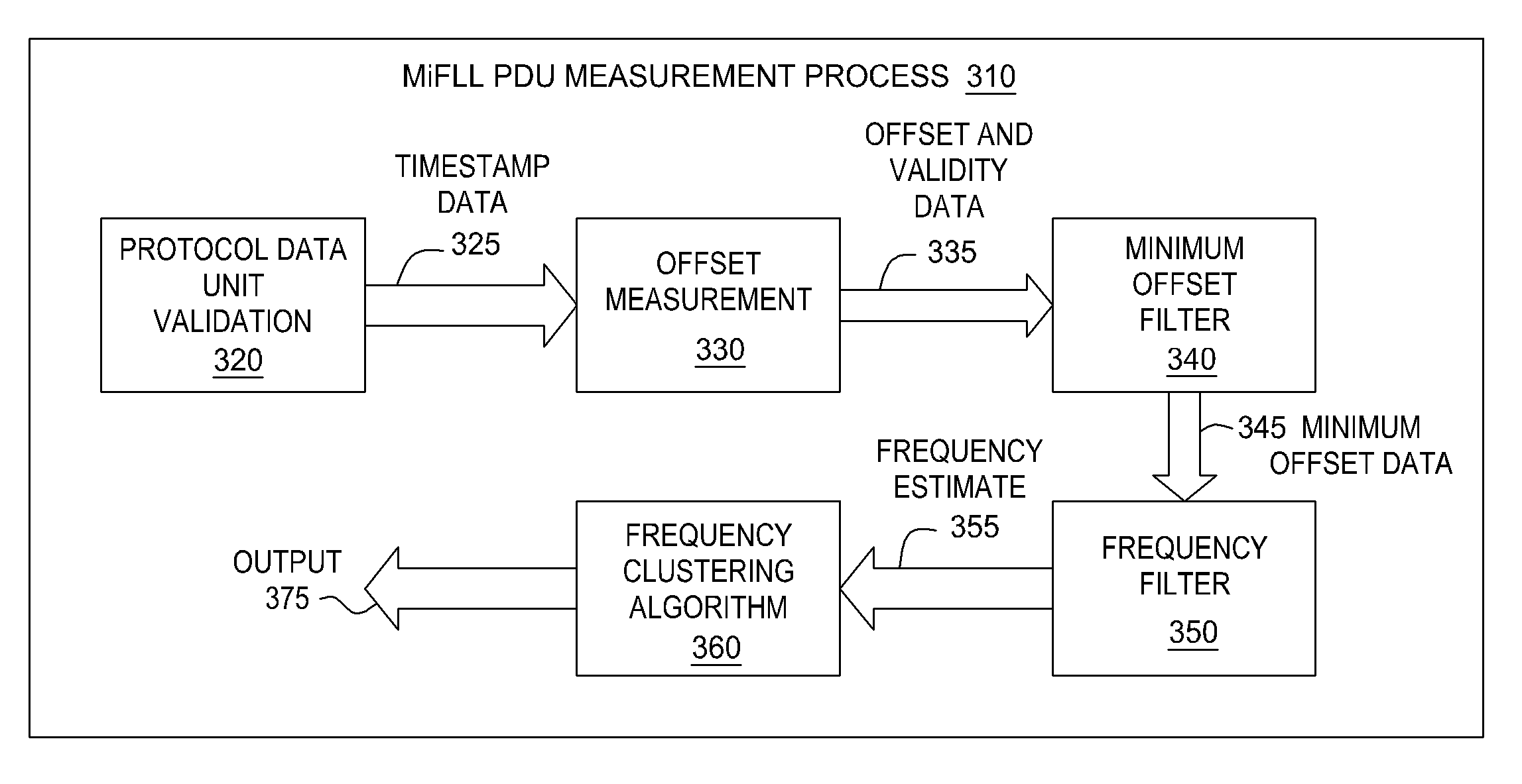
"The present invention provides a method for validating the time and frequency information received from a server clock and generating a frequency estimate between a client clock and the server clock. This is achieved by receiving at least two protocol data units (PDUs) with time stamps, extracting the time stamps, performing offset measurements based on the time stamps, and performing minimum offset filtering and frequency estimate filtering to produce a stable frequency estimate. The method allows for the control of the client clock using less trustworthy timing sources, such as multicast NTP and multicast PTP servers, while still extracting accurate time and frequency information. This reduces costs for both the servers and clients."

Problems solved by technology

While quartz oscillators offer good frequency stability over short term measurement intervals, their intermediate and long term frequency stability does not meet the telecommunications standards.
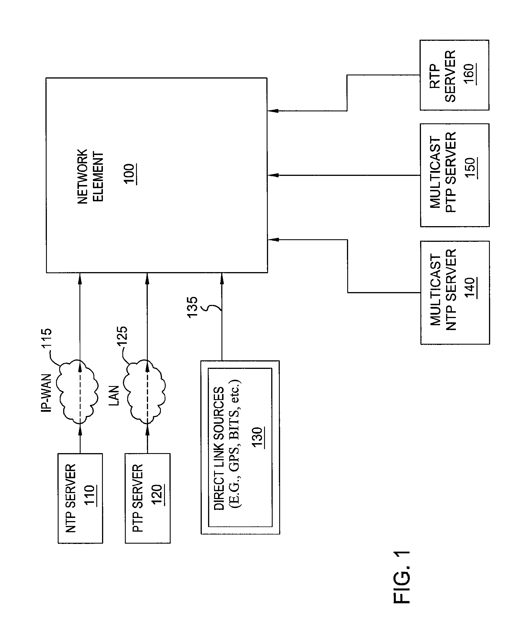
However, next generation networks may be based on a packet-switched infrastructure (such networks are referred herein as “packet networks”) and there may be situations where the physical medium interconnecting network elements is no longer capable of transporting frequency information at the physical layer.
Also, their frequency stability is not always satisfactory for the telecommunications standard.
However, extracting time and frequency information from the multicast NTP and PTP flows creates several problems.
First, it is not always known if these flows are sourced from a reliable server clock.
As a result, inaccurate data may be sent to the MiFLL, compromising the performance of a client clock.

Method used


Image

  • Enhanced clock control in packet networks
  • Enhanced clock control in packet networks
  • Enhanced clock control in packet networks

Examples


Embodiment Construction

[0020]The present invention improves upon the teachings of U.S. Pat. No. 5,751,777 and U.S. Pat. No. 5,943,381, the entire contents of both of which are incorporated herein by reference for all purposes.

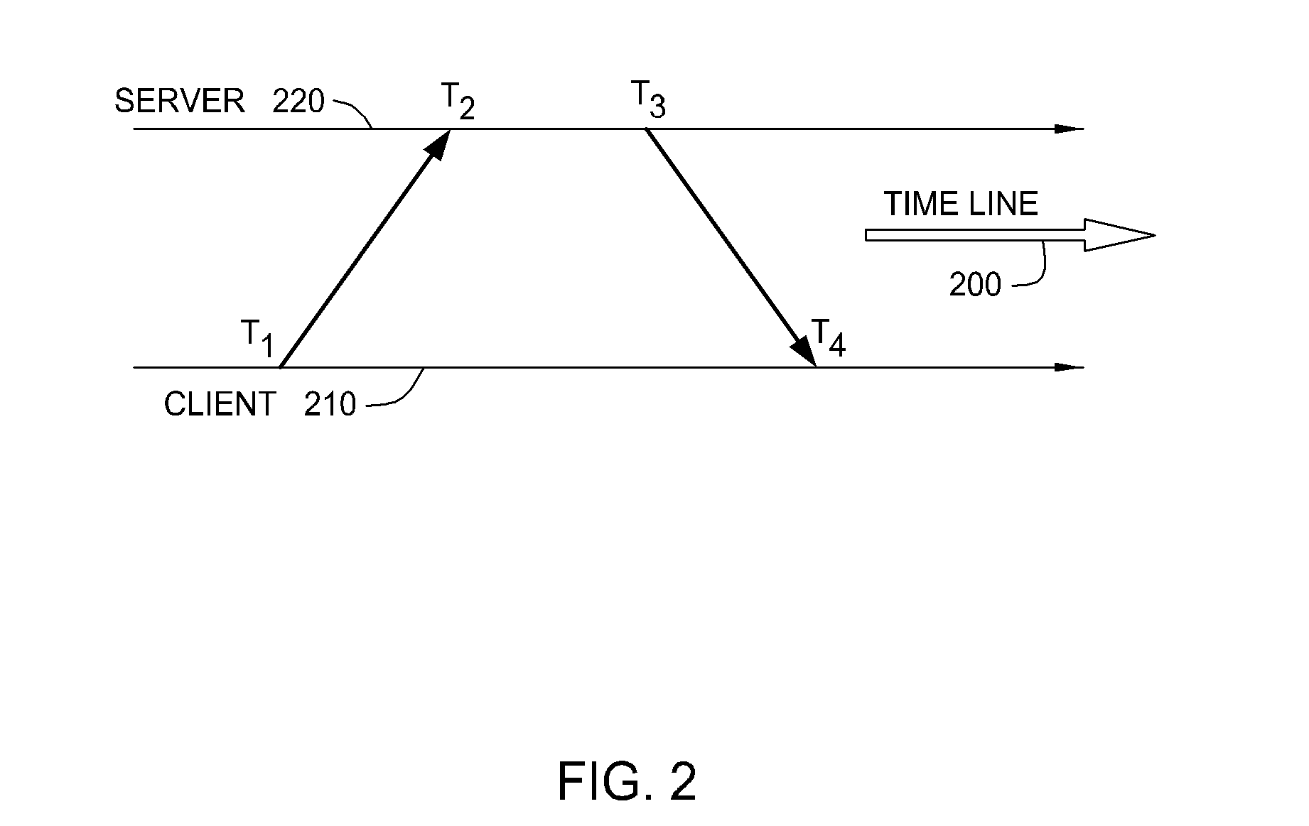
[0021]FIG. 2 illustrates the notions of time stamps, according to one embodiment of the present invention. Both the primary tier and the secondary tier sources utilize variants of a time stamping process illustrated in FIG. 2. As shown, a time measurement process may involve four time stamps along a timeline 200, which are defined as follows:

T1 is a time stamp representing the best estimate of the transmit origination epoch of a protocol data unit (PDU) originating from the clock of a client 210,

T2 is a time stamp representing the best estimate of the receive termination epoch of a PDU terminating at the clock of a server 220,

T3 is a time stamp representing the best estimate of the transmit origination epoch of a PDU originating from the clock of the server 220, and

T4 is a time stamp...


PUM


Abstract

One embodiment of the present invention sets forth a method for autonomously validating the time and frequency data obtained from multiple sources, and generating a suitable estimate of the frequency difference between the client clock and the source. The method includes the steps of protocol data unit validation, offset measurement, minimum offset filtering, and frequency filtering. With these steps, the negative effects of packet delay variation may be mitigated and a frequency estimate is determined for the source in question, together with an associated validity status. Consequently, quality control of the local clock is achieved in packet networks at significantly reduced cost and decreased level of complexity relative to prior art approaches.

Description

CROSS-REFERENCE TO RELATED APPLICATIONS[0001]This application claims benefits of the U.S. provisional application Ser. No. 60 / 763,967, filed Feb. 1, 2006, which is herein incorporated by reference. This application is also related to U.S. Pat. No. 5,751,777 and U.S. Pat. No. 5,943,381, which are herein incorporated by reference.BACKGROUND OF THE INVENTION[0002]1. Field of the Invention[0003]Embodiments of the present invention generally relate to methods of controlling the clock of a network element deployed within a communications network and, more specifically, to enhanced clock control in packet networks.[0004]2. Description of the Related Art[0005]In many telecommunications applications, each element in the network has its own clock (referred to herein as a “client clock”) running independently of the other clocks in the network. Quartz oscillators typically serve as client clocks in network elements, providing frequency to support local timescale generation. While quartz oscill...

Claims


Application Information

Patent Timeline
Patent Type & Authority Patents(United States)
IPC IPC(8): H04J3/06G04G5/00
CPCG04G5/00G06F1/14H04J3/0667H04L69/28H04J3/14H04L7/00H04J3/06
Inventor ZAMPETTI, GEORGE P.
Owner MICROSEMI FREQUENCY & TIME
Learn More