Device and method for reduction of a gas component in an exhaust gas flow of a combustion engine

a technology of combustion engine and gas component, which is applied in the direction of exhaust treatment, phosphorus compounds, electrical control, etc., can solve the problems of no/sub>x/sub>compound reduction, no proper utilization of three-way catalysts, and surplus fuel supply, so as to reduce the amount of nox compounds. the effect of the engine discharg

Inactive Publication Date: 2011-11-29
VOLVO TECH
View PDF22 Cites 81 Cited by
  • Summary
  • Abstract
  • Description
  • Claims
  • Application Information

AI Technical Summary

Benefits of technology

[0026]According to the third embodiment of the invention, a component in the form of water can be separated from the exhaust gas flow and be returned to the intake side of the engine. This contributes to a decrease of the amount of NOx compounds which are formed in the engine. In this manner, the invention provides a “selective EGR function” with return of water that is separated from the exhaust gases in the wall structure. One advantage related to this arrangement is that no extra water needs to be supplied to the engine for decrease of NOx compounds, but instead the amo

Problems solved by technology

This results in the three-way catalyst not being properly utilized for reduction of the NOx compounds in the exhaust gases due to the fact that it is constructed for an optimal purification capacity during stoichiometric mixture.
Although the above-mentioned course of events for regeneration of a NOx adsorbent in principle functions satisfactorily, it suffers from certain drawbacks.
Moreover, the regeneration results in a surplus of fuel being supplied to the engine during the rich pulse.
This in turn causes the engine's fuel consumption to be influenced in a negative way.
An additional drawback associated with the regeneration of a NOx adsorbent by means of supply of a reduction agent is that

Method used


Image

  • Device and method for reduction of a gas component in an exhaust gas flow of a combustion engine
  • Device and method for reduction of a gas component in an exhaust gas flow of a combustion engine
  • Device and method for reduction of a gas component in an exhaust gas flow of a combustion engine

Examples


second embodiment

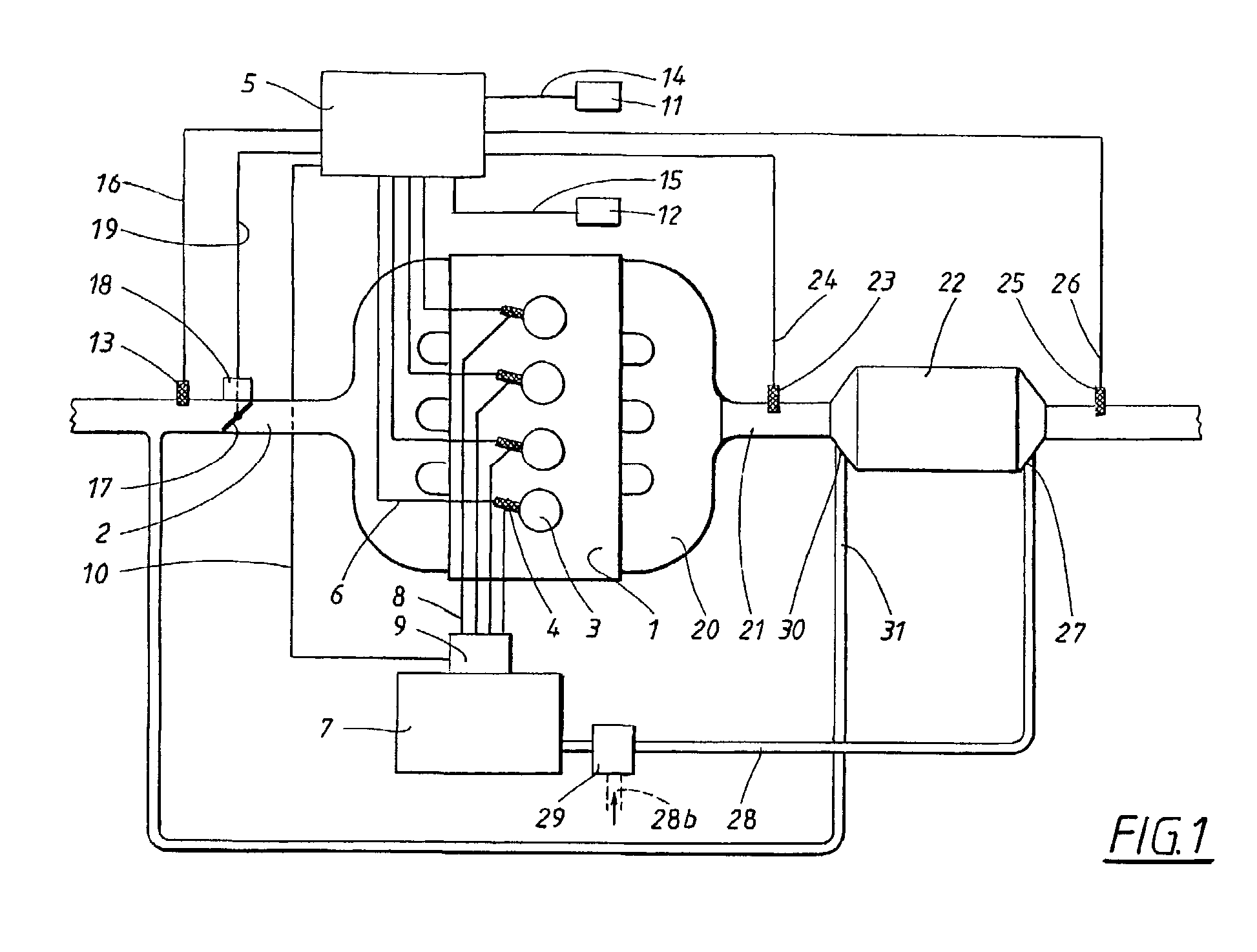
[0068]In the following, the invention is described with reference to the FIG. 4, which essentially corresponds to FIG. 1, but that does not include any supply of a reduction agent. Moreover, it can be noted that the same reference numerals are used in FIG. 4 for the components that also are apparent from FIG. 1.

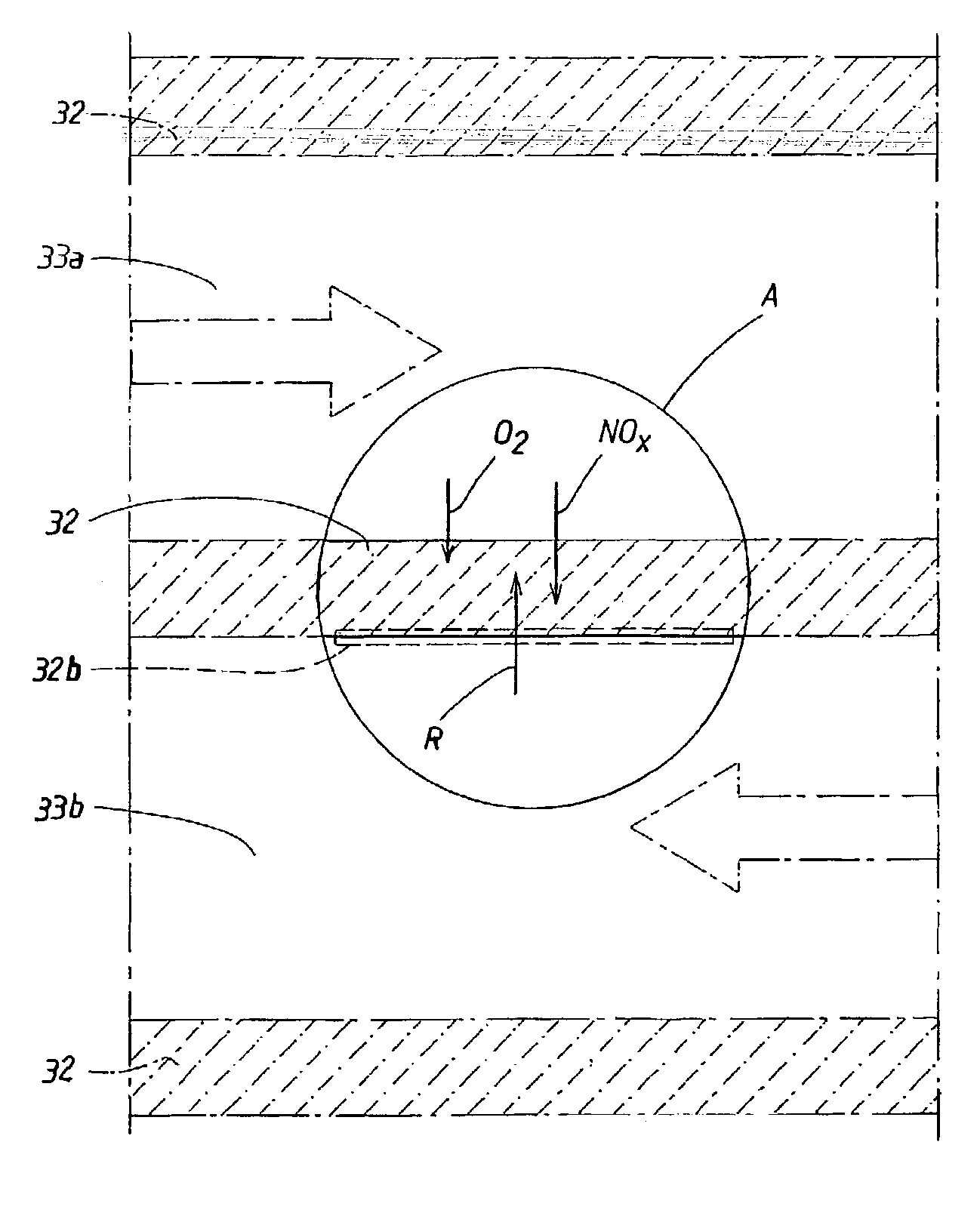
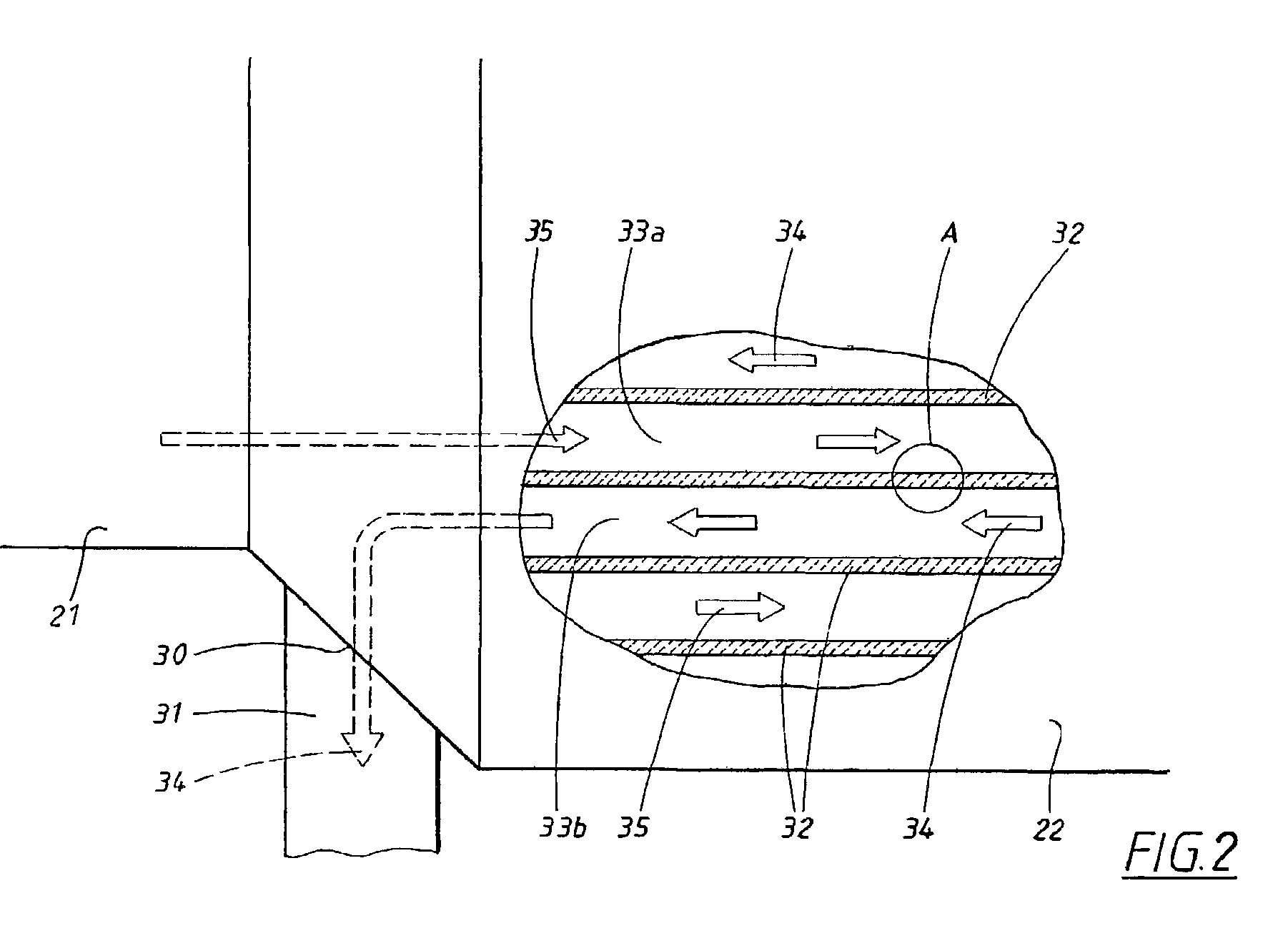
[0069]According to what is apparent from FIG. 4, the separation unit 22 is connected with the inlet 2 of the engine 1 in a manner that corresponds to the above-mentioned embodiment; for example, via a conduit 31. Unlike the embodiment according to FIG. 1, however, in which the conduit 31 is utilized for return of any possible unutilized reduction agent to the engine 1, the conduit 31 in the embodiment according to FIG. 4 is utilized for return of NOx compounds that have been separated from the engine exhaust gases by means of the separation unit 22. In this case, the separation of NOx compounds takes place in a manner that corresponds to what has been explained above with ref...

third embodiment

[0072]It is known that a supply of water provided to a combustion engine decreases the generation of NOx compounds in the engine. This principle is utilized in the third embodiment in so far as a certain amount of water is separated from the exhaust gas flow in the separation unit and is subsequently returned to the air inlet 2 of the engine 1, via a return conduit 31 that is intended for return of water.

fourth embodiment

[0073]the invention is shown in FIG. 5. FIG. 5 is a slightly simplified principal diagram of an engine system which essentially corresponds to what has been described above, but which is intended for an engine 1 which is provided with a turbo-aggregate 36, which in turn includes an exhaust gas operated turbine 37 and a compressor 38 by means of which inflowing air is compressed. To this end, the turbine 37 and the compressor 38 are arranged on a common axle 39 in a known manner, wherein the compressor 38 is operated by the turbine 37 that is in turn operated by the exhaust gases that flow from the engine 1. Moreover, the system includes a so-called “intercooler”40, by means of which the air, which has been fed through the compressor 38 and to the engine 1, can be cooled.

[0074]According to what is apparent from FIG. 5, the engine 1, via its exhaust pipe 21, is connected with a separation unit 22 of the corresponding type that has been described above. The exhaust gases from the engin...


PUM

PropertyMeasurementUnit
Flow rateaaaaaaaaaa
Transport propertiesaaaaaaaaaa
Reduction potentialaaaaaaaaaa

Abstract

Method and device for reduction of a gas component in an exhaust gas flow of a combustion engine (1) that is adapted for operation by a lean air/fuel mixture. An exhaust pipe (21) is included for transport of the exhaust gas flow from the engine (1). A separation unit (22) is also included that is arranged along the exhaust pipe (21), which separation unit (22) has a wall structure (32) of a material which provides separation of the gas component from the exhaust gas flow by means of a selective passage of the gas component before other gas components in the exhaust gas flow. The method provides for a reduction and a separation unit that is intended to be utilized during such a reduction. An improved reduction of in particular NOx compounds from a so-called “lean-burn” engine is also provided.

Description

CROSS REFERENCE TO RELATED APPLICATIONS[0001]The present application is a continuation of International Application No. PCT / SE01 / 00934, filed Apr. 30, 2001 and published in English pursuant to PCT Article 21(2), now abandoned, and which claims priority to Swedish Application No. 0001 587-5 filed May 2, 2000. Both applications are expressly incorporated herein by reference in their entireties.BACKGROUND OF INVENTION[0002]1. Technical Field[0003]The present invention relates to a device for reducing at least one gas component in an exhaust gas flow of a combustion engine. The engine is adapted for operation on a lean air / fuel mixture and includes an exhaust pipe for transport of the exhaust gas flow from the engine. The invention is particularly intended for reduction of harmful emissions from the exhaust gas flow; and more particularly, via a method and arrangement incorporating a separation unit for this purpose.[0004]2. Background of the Invention[0005]In the field of vehicles that...

Claims


Application Information

Patent Timeline
IPC IPC(8): F01N3/00B01D53/22B01D53/92F02M25/07B01D53/94F01N3/08F01N3/20F01N3/28F01N3/30F01N3/36F01N11/00F02D21/08F02D23/00F02D41/04F02D45/00
CPCB01D53/229B01D53/9431F01N3/0807F01N3/0814F01N3/0842F01N3/0871F01N11/00F01N11/007F02M25/0718B01D53/92Y02T10/47F01N2370/00F01N2370/24F01N2570/14F01N2610/03F02M25/0704F02M26/02F02M26/15Y02A50/20Y02T10/40
Inventor JOBSON, EDWARDCIDER, LENNARTWIRMARK, GORAN
Owner VOLVO TECH
Why Eureka
Try Eureka