Lighting device employing a light guide plate and a plurality of light emitting diodes

a light guide plate and light-emitting diode technology, which is applied in the direction of lighting and heating apparatus, planar/plate-like light guides, instruments, etc., can solve the problems of degrading the lumen efficiency of such a lighting device and insufficient light of a single led, so as to reduce the probability of light loss, prevent interactions, and promote out-coupling

Active Publication Date: 2011-11-29
SIGNIFY HLDG BV
View PDF9 Cites 3 Cited by
  • Summary
  • Abstract
  • Description
  • Claims
  • Application Information

AI Technical Summary

Benefits of technology

[0006]It is an object of the present invention to overcome or at least alleviate this problem, and to provide a lighting device with improved lumen efficiency.
[0008]By means of the hole structure with a corner between two in-coupling side facets, light from a LED arranged in the hole may be split up in sub-beams, each of which is more or less perpendicular to its originating side facet, allowing control of the direction of the light to prevent light from entering adjacent holes. As a result, losses due to absorption or scattering at adjacent light sources in the lighting device can be diminished, and the luminous efficiency of the lighting device can be increased. To this end, preferably, the holes are arranged such that the sub-beams will reflect off the side facets of an adjacent hole, and consequently not enter the adjacent hole.
[0009]For instance, in one embodiment, a corner of the at least one corner of one hole points towards an adjacent hole. That is, preferably, the extension of an imaginary line between the center and the corner of the hole traverses the adjacent hole. By pointing a corner of a hole in a given direction, less light will be sent to that direction. Therefore, light coupled into the light guide plate through the in-coupling side facet of one hole generally (if ever) hits the side facet(s) of the adjacent hole at larger angles of incidence (compared to the prior art case discussed above, for example), thereby increasing the probability of total internal reflection (TIR) at the side facet of the adjacent hole so that the light does not enter that hole.
[0014]The light guide plate can further have means for aiming light emitted from the LEDs towards areas of the light guide plate free from holes. The directing means can for example comprise slits or other reflecting elements. In one embodiment, wherein an LED array is arranged along a reflective edge of the light guide plate, the directing means comprises slits arranged such that light reflected by the edge is aimed towards the spaces between the holes of the array, thereby significantly decreasing the probability that light is lost at nearby light sources. In a specific embodiment, the light guide plate has the shape of a right triangle wherein one cathetus of the triangular light guide plate is formed by the reflective edge along which the LEDs are placed. The other cathetus is preferably also a reflective edge and the hypotenuse preferably comprises an out-coupling structure for coupling light out of the light guide plate, as discussed above. Such a triangular lighting device has a uniform and collimated light distribution. In another embodiment, wherein two LED arrays are arranged along each other, the directing means comprises slits arranged such that light from one array is aimed towards the spaces between the holes of the other array, thereby significantly decreasing the probability that light is lost at nearby light sources.

Problems solved by technology

For many lighting applications, the light of a single LED is not sufficient, and light of multiple LEDs needs to be combined to form a light source.
Thus, the lumen efficiency of such a lighting device is degraded.

Method used


Image

  • Lighting device employing a light guide plate and a plurality of light emitting diodes
  • Lighting device employing a light guide plate and a plurality of light emitting diodes
  • Lighting device employing a light guide plate and a plurality of light emitting diodes

Examples


Embodiment Construction

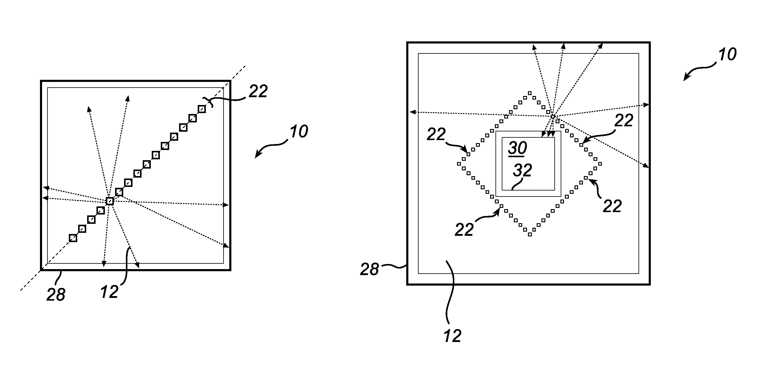
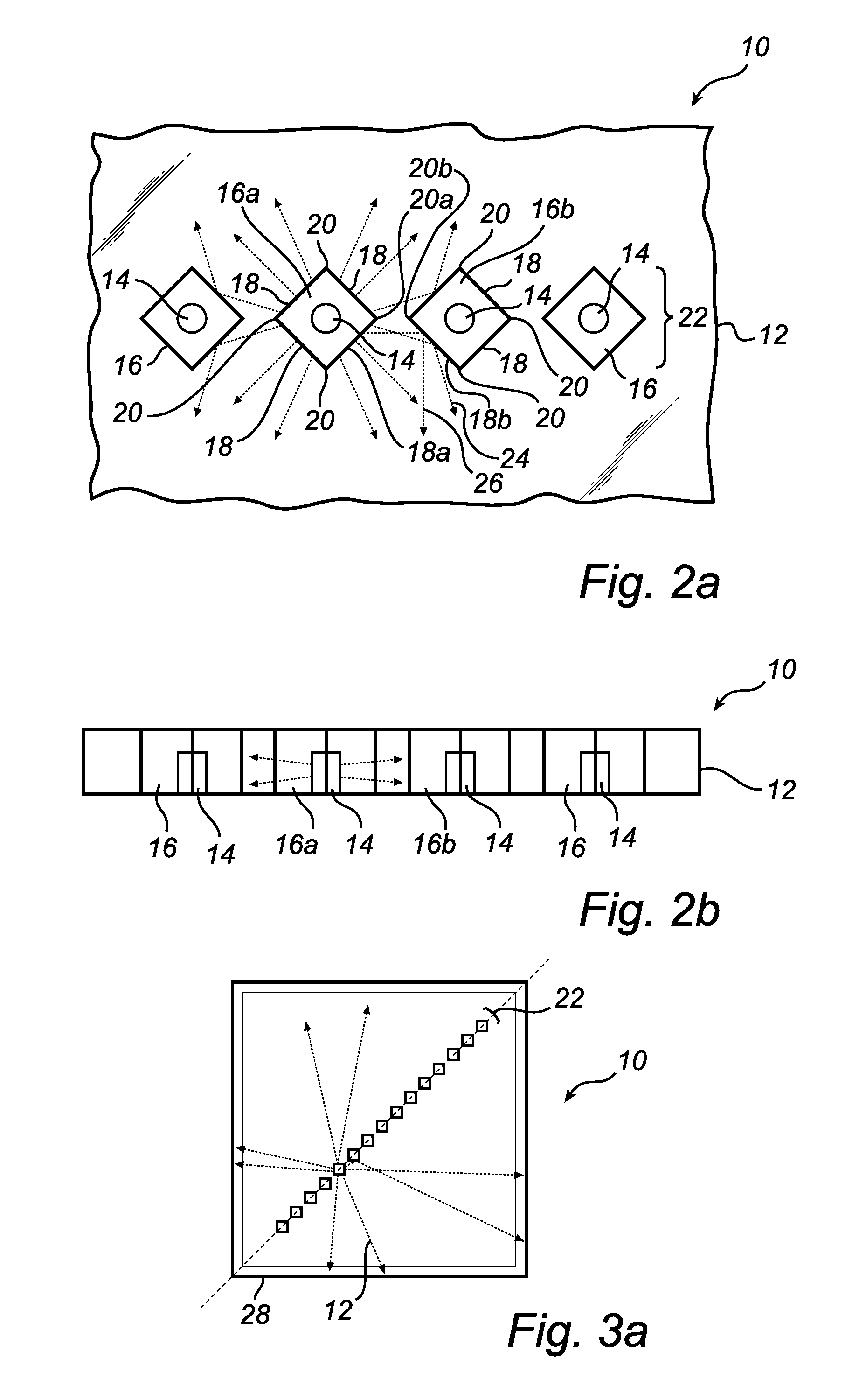
[0028]A light emitting diode (LED) based lighting device according to an embodiment of the present invention will now be described with reference to FIGS. 2a-2b. The lighting device denoted 10 comprises a light guide plate 12. The light guide plate 12 is transparent and can be made of glass or plastics, for example.

[0029]The lighting device 10 further comprises a plurality of LEDs generally designated 14 accommodated in holes generally designated 16 and arranged in the light guide plate 12. The holes 16 could be through holes (as in FIG. 2b) or holes having an opening towards one side of the light guide plate 12 only. The LEDs 14 are preferably side-emitting omnidirectional LEDs. Alternatively, unidirectional LEDs or clusters of unidirectional LEDs that are aimed in opposite directions can be used.

[0030]Each hole 16 in the embodiment illustrated in FIGS. 2a-2b is square-shaped with four in-coupling side facets generally designated 18. Between each two adjoining in-coupling side face...


PUM

PropertyMeasurementUnit
angleaaaaaaaaaa
angle of departureaaaaaaaaaa
shapeaaaaaaaaaa

Abstract

The present invention relates to lighting device (10). The lighting device comprises a light guide plate (12), and at least one array of light emitting diodes (LEDs) (14), which LEDs are accommodated in holes arranged in the light guide plate, wherein each hole has: at least two side facets (18) through which light from the LEDs is to be laterally coupled into the light guide plate, and at least one corner (20) formed by two converging side facets of the at least two side facets. This promotes TIR at adjacent light sources and therefore diminishes losses due to absorption or scattering at adjacent holes.

Description

[0001]This application is a national stage application under 35 U.S.C. §371 of International Application No. PCT / IB2007 / 054104 filed on Oct. 9, 2007, which claims priority to European Application No. 06122321.0, filed on Oct. 16, 2006, and European Application No. 07100359.4 filed on Nov. 1, 2006, both incorporated herein by reference.FIELD OF THE INVENTION[0002]The present invention relates to lighting device comprising a light guide plate and a plurality of light emitting diodes.BACKGROUND OF THE INVENTION[0003]Progress in the brightness, lumen efficacy and affordability of solid state light sources such as light emitting diodes (LEDs) enables new lighting applications that are no longer restricted to niche markets. LEDs offer several advantages over traditional light sources, such as long lifetime, low operating voltage, instant on, etc. For these and other reasons, LEDs are becoming more and more suited for making lamps for several applications such as color variable lamps, spot...

Claims


Application Information

Patent Timeline
Patent Type & Authority Patents(United States)
IPC IPC(8): F21V8/00
CPCG02B6/002G02B6/0068G02B6/0023G02B6/0021
Inventor VISSENBERG, MICHEL CORNELIS JOSEPHUS MARIEDEKKER, TIMIJZERMAN, WILLEM LUBERTUSBERGMAN, ANTHONIE HENDRIK
Owner SIGNIFY HLDG BV
Why Eureka
Try Eureka