Combination electrical stimulating and infusion medical device and method

a technology of electrical stimulation and infusion catheter, which is applied in the field of medical devices and methods for treating medical conditions, to achieve the effects of reducing the risk of infection, preventing inadvertent buckling or displacement of leads, and preventing backflow of infusion materials

Active Publication Date: 2011-11-29
NEUROTHERM
View PDF79 Cites 144 Cited by
  • Summary
  • Abstract
  • Description
  • Claims
  • Application Information

AI Technical Summary

Benefits of technology

[0016]With respect to treatment of an intervertebral disc, the stimulation device is in the form of a stimulation lead designed to be placed in the disc percutaneously through an introducer needle using an extra-pedicular approach; however, micro-surgical or open-surgical techniques may also be utilized. More specifically, the device of the present invention is specifically designed to facilitate placement proximate to the metabolically active cellular, nuclear, annular interface layer by use of one or more selected embodiments including a straight, curved or bent tip, as well as a variable stiffness tip. Selection of one of these embodiments allows the physician to precisely navigate the lead through the nucleus of the disc. In yet another embodiment of the present invention, the stimulation lead may be placed directly into the nuclear annular interface by use of an introducer needle having a bent tip, and use of a stimulation lead having a straight tip that can take a substantially linear path to reach the target tissue.
[0024]In yet another embodiment of the invention, an inflatable member may be used with a stimulation lead such that the inflatable member can shift or adjust the exact positioning of the stimulation lead to more accurately apply the electrical or thermal energy to the targeted area.

Problems solved by technology

In some embodiments, the electrodes extend circumferentially around a selected length or portion of the lead since it is difficult to orient a specific lateral side of the lead against target tissue.

Method used


Image

  • Combination electrical stimulating and infusion medical device and method
  • Combination electrical stimulating and infusion medical device and method
  • Combination electrical stimulating and infusion medical device and method

Examples


first embodiment

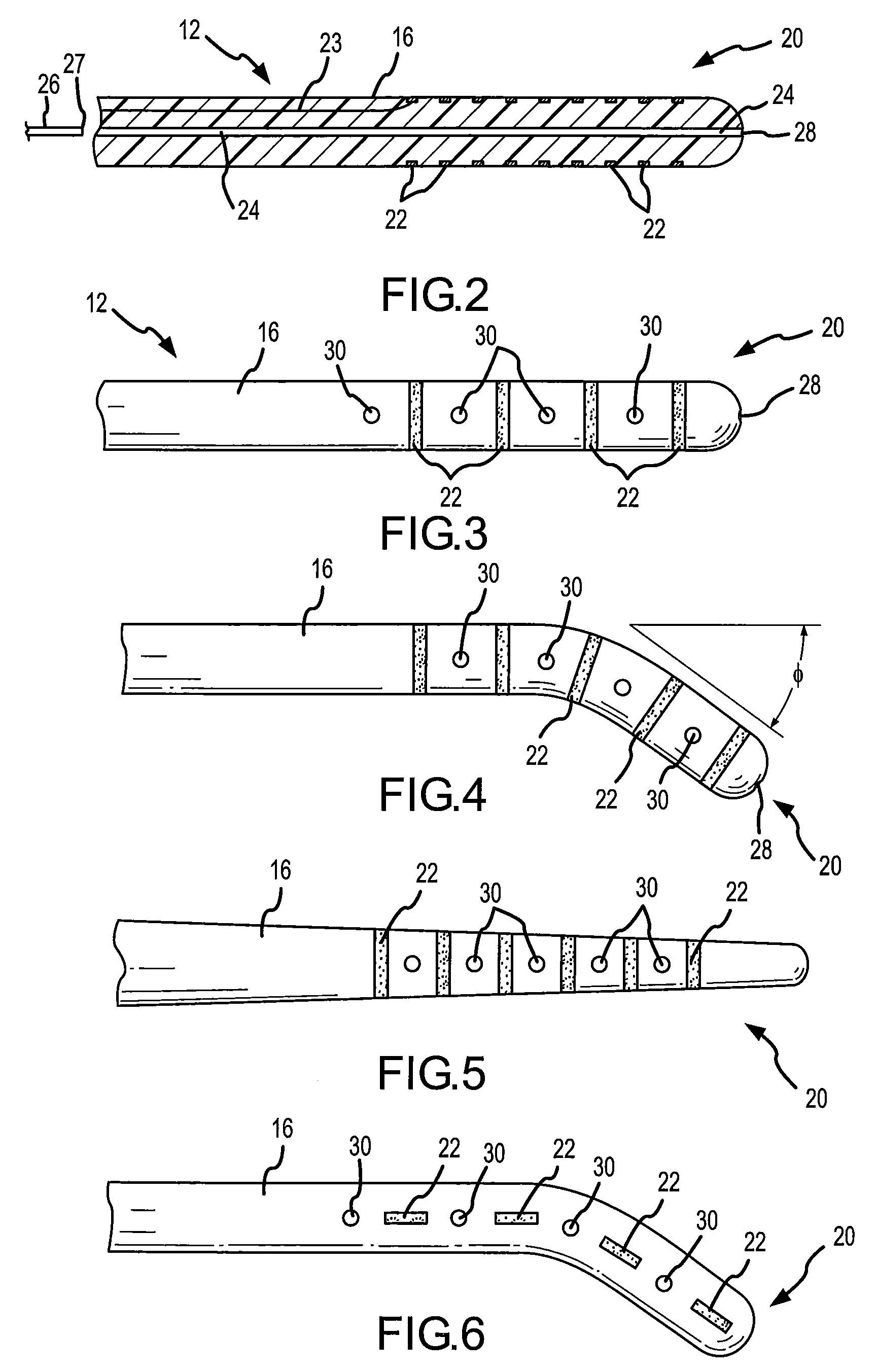
[0081]Referring specifically to FIG. 2, in the stimulation lead, a plurality of circumferentially extending electrodes 22 are positioned at the distal portion 20. The electrodes 22 are also spaced longitudinally along the distal portion 20. The electrodes produce an array of electrical field energy, and the target tissue is immersed in the electrical field. One or more electrical conductors 23 extend through the interior of the stimulation lead 16 in order to transmit the electrical impulses to the electrodes 22. It is preferable to utilize a single conductor 23 along the major length of the lead, and then provide branch conductors (not shown) at the distal portion 20 that then extend to contact the various electrodes. The branch conductors could be a linearly arranged set of wire extensions extending between each electrode, or any other advantageous combination of wire conductors to interconnect the electrodes. Use of a single conductor is a more robust design as opposed to multipl...

embodiment 310

[0120]Referring to FIG. 34, this alternative sheath embodiment 310 is characterized by a very flexible body 312 having a plurality of slots or openings 314 formed therein. A distal end of the body 312 includes a tip 316. The tip can be blunt or sharp, depending upon the intended use. Referring to FIG. 35, electrodes 318 are cylindrical shaped sections that are slipped over the body 312, in the same manner as disclosed with respect to FIG. 28. However, in the case of FIG. 35, a bracket 320 is used to interconnect the electrodes from the reusable stimulation lead with the electrodes 318 formed on the sheath. As shown, the bracket 320 may include a pair of traverse flanges 322, sidewalls 326, and base 328. Accordingly, a channel 324 is formed between the sidewalls and base. The bracket 320 is placed in a corresponding slot 314 such that the flanges 322 rest on the outer surface of the body 312. When the electrode 318 is slipped over the body 312, the electrode 318 is aligned such that ...


PUM

PropertyMeasurementUnit
RF energyaaaaaaaaaa
temperatureaaaaaaaaaa
lengthaaaaaaaaaa

Abstract

A combined electrical and chemical stimulation lead is especially adapted for providing treatment to the spine and nervous system. The stimulation lead includes electrodes that may be selectively positioned along various portions of the stimulation lead in order to precisely direct electrical energy to ablate or electrically stimulate the target tissue. The invention also includes a method of activating electrodes in the electrical stimulation lead whereby an ablative lesion can be formed in a desired shape and size. The invention further includes a method of managing pain in a sacrum of a patient, and a method of assembling an electrical stimulation device.

Description

CROSS REFERENCE TO RELATED APPLICATION[0001]This application is a Continuation-in-Part of co-pending application Ser. No. 11 / 771,757 filed on Jun. 29, 2007 entitled “COMBINATION ELECTRICAL STIMULATING AND INFUSION MEDICAL DEVICE”, which is a Continuation-in-Part of co-pending application Ser. No. 11 / 678,516 filed on Feb. 23, 2007 entitled “COMBINATION ELECTRICAL STIMULATING AND INFUSION MEDICAL DEVICE”, which is a Continuation-in-Part of co-pending application Ser. No. 11 / 107,553, filed on Apr. 14, 2005, entitled “COMBINATION ELECTRICAL STIMULATING AND INFUSION MEDICAL DEVICE”, which is a Continuation-in-Part of co-pending application Ser. No. 11 / 033,591, filed on Jan. 11, 2005, entitled “COMBINATION ELECTRICAL STIMULATING AND INFUSION MEDICAL DEVICE”, the disclosures of which are hereby incorporated by reference herein.TECHNICAL FIELD OF THE INVENTION[0002]The present invention relates generally to electrical stimulation leads and chemical infusion catheters for treatment of medica...

Claims


Application Information

Patent Timeline
Patent Type & Authority Patents(United States)
IPC IPC(8): A61B18/18
CPCA61B18/1477A61N1/36071A61B18/1492A61M25/007A61N1/0551A61M25/0043A61B2018/0044Y10T29/49208A61N1/0558A61N1/36017
Inventor RITTMAN, III, WILLIAM J.VILIMS, BRADLEY D.
Owner NEUROTHERM
Why Eureka
Try Eureka