Systems and methods for multi-function coherent imaging

a coherent imaging and multi-function technology, applied in the field of imaging, can solve the problems of -frame rate or high pixel rate, complicated subsequent processing,

Active Publication Date: 2011-11-29
LOCKHEED MARTIN CORP
View PDF7 Cites 22 Cited by
  • Summary
  • Abstract
  • Description
  • Claims
  • Application Information

AI Technical Summary

Benefits of technology

[0006]In accordance with one aspect, exemplary digital holographic systems and methods of the present invention may be used for performing coherent detection and imaging. Such systems and methods may utilize multiple frames of coherent data for image formation, including the formation of three-dimensional images. Such systems and methods may also record multiple coherent images simultaneously. They may also utilize high-density, low-speed detector arrays to spatially encode information, rather than using expensive high-speed detector arrays.
[0007]In accordance with one aspect of the present invention, multiple coherent images may be simultaneously recorded by using different spatial carrier frequencies for two or more radiation beams. In one aspect of the present invention, multi-wavelength data, multi-spectral data, multi-polarization data, or any combination thereof may be recorded. In addition, moving objects may be imaged.
[0008]An exemplary embodiment relates to a multi-function coherent imaging system, comprising a first coherent radiation source configured to output a first radiation beam, and a second coherent radiation source configured to output a second radiation beam. The exemplary system f

Problems solved by technology

One difficulty in performing serial detection in realistic conditions is that slight object motion, on the order of the wavelength of light, can introduce phase decorrelation in the data that complicates subsequent processing or makes such processing impossible.
Systems designers are forced

Method used


Image

  • Systems and methods for multi-function coherent imaging
  • Systems and methods for multi-function coherent imaging
  • Systems and methods for multi-function coherent imaging

Examples


Embodiment Construction

[0037]In the following detailed description, numerous specific details are set forth to provide a full understanding of the present invention. It will be obvious, however, to one ordinarily skilled in the art that the present invention may be practiced without some of these specific details. In other instances, well-known structures and techniques have not been shown in detail not to obscure the present invention.

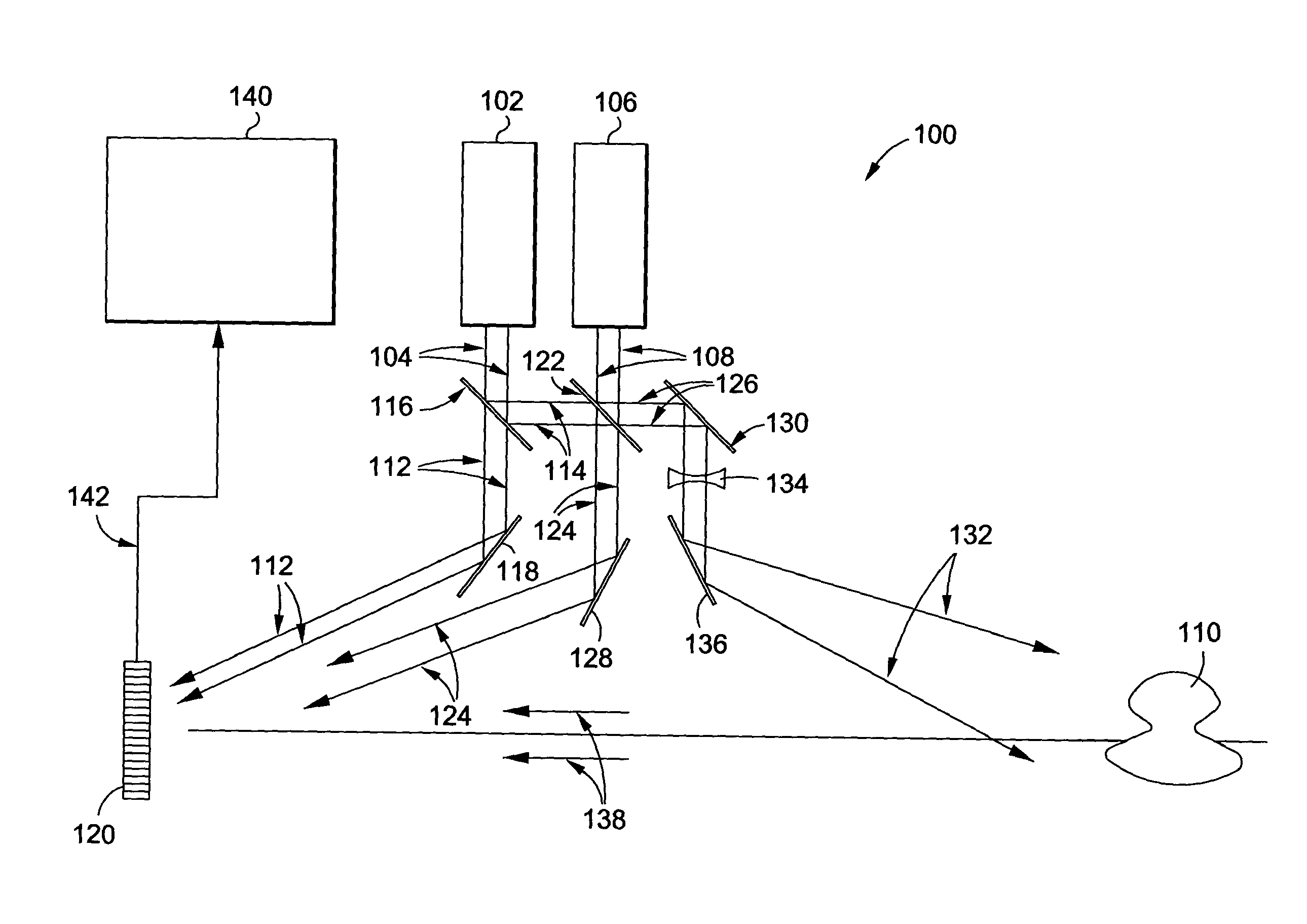
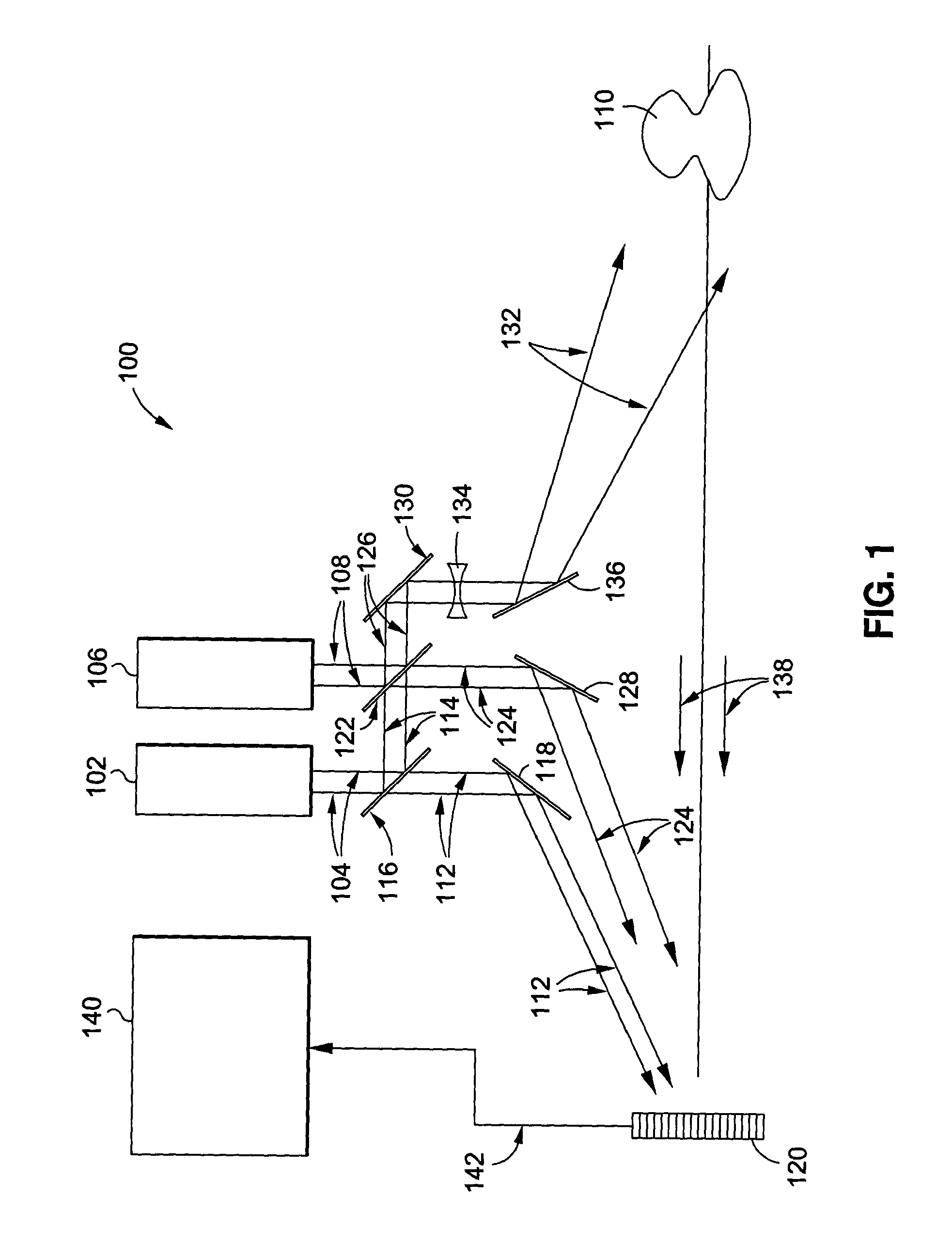
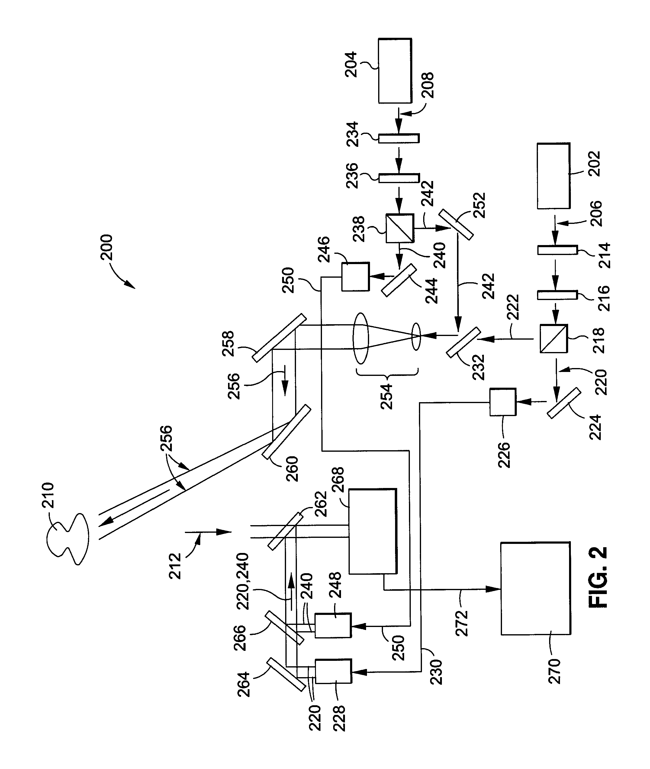
[0038]According to one aspect of the present invention, a plurality of sources of coherent radiation may output one or more radiation beams, which may be divided into reference radiation beams and object illumination beams. The radiation beams from the coherent radiation sources may be pulsed beams or continuous wave beams. The plurality of coherent radiation sources are preferably tunable lasers capable of producing radiation with wavelengths greater than or equal to about 800 nm and with optical power of about one watt or greater. The object illumination beams may radiate...


PUM


Abstract

Systems and methods are provided for multi-function coherent imaging comprising directing a first coherent radiation beam and a second coherent radiation beam towards a detector, where the second coherent radiation beam is spatially offset, angularly offset, or spatially and angularly offset from the first coherent radiation beam. A portion of the first coherent radiation beam and a portion of the second coherent radiation beam may be combined to form a composite beam. An object may be radiated with the composite beam. A first intensity pattern may be formed by interfering with return radiation from the radiated object with the first coherent radiation beam and a second intensity pattern is formed with the return radiation from the radiated object and the second coherent radiation beam. A detector may simultaneously record a superposition of the first intensity pattern and the second intensity pattern.

Description

STATEMENT AS TO RIGHTS TO INVENTIONS MADE UNDER FEDERALLY SPONSORED RESEARCH OR DEVELOPMENT[0001]Not Applicable.FIELD OF THE INVENTION[0002]The present invention generally relates to imaging and, in particular, relates to multi-function coherent imaging.BACKGROUND OF THE INVENTION[0003]In the field of laser remote sensing and imaging, an object is typically radiated with a laser source, and the reflected light intensity is measured to determine the characteristics of the object. Typically, the object is spatially scanned with a narrow laser beam, and the intensity of the reflected beam is measured as a function of beam location. Alternatively, the object can be flood illuminated with laser light and the image can be recorded by using a detector array with a conventional lens in a manner analogous to flash photography.[0004]One method for performing image detection requires serially illuminating an object with the desired laser frequencies or other discriminants and recording the dat...

Claims


Application Information

Patent Timeline
IPC IPC(8): G01B11/02
CPCG03H1/0443G03H1/08G03H1/265G03H2001/0445G03H2001/045G03H2222/13G03H2222/34G03H2223/12G03H2223/16
Inventor MARRON, JOSEPH C.KENDRICK, RICHARD L.
Owner LOCKHEED MARTIN CORP
Why Eureka
Try Eureka