Thermal flowmeter

a flowmeter and flow rate technology, applied in the field of thermal flowmeters, can solve the problems of affecting the accuracy of thermal flowmeters, so as to suppress the degradation of characteristics and maintain high measurement accuracy over a long period of time.

Active Publication Date: 2011-12-06
HITACHI ASTEMO LTD
View PDF25 Cites 22 Cited by
  • Summary
  • Abstract
  • Description
  • Claims
  • Application Information

AI Technical Summary

Benefits of technology

[0011]It is an object of the present invention to realize a simply configured thermal flowmeter capable of keeping high measurement accuracy over a long period of time by suppressing the characteristics degradation due to adhering contaminants.
[0018]According to the present invention, it is possible to realize a simply configured thermal flowmeter capable of keeping high measurement accuracy over a long period of time by suppressing the characteristics degradation due to adhering contaminants.

Problems solved by technology

However, if a thermal flowmeter is used to detect, for example, the amount of air taken into an automobile internal combustion engine, oil, dust and other contaminants in the intake air collide with and adhere to the sensor device, resulting in measurement errors.
Especially, when an object has a portion on its surface that undergoes a rapid temperature change from low to high temperature, contaminants are more likely to deposit on that portion.
However, since the above-mentioned conventional technique gives no consideration to adhering contaminants, the characteristics change of the sensor device due to the contamination has been a factor impeding the improvement of thermal flowmeters in measurement accuracy.

Method used


Image

  • Thermal flowmeter
  • Thermal flowmeter
  • Thermal flowmeter

Examples


first embodiment

[0032]First, the following describes the basic configuration and operation principle of a thermal flowmeter according to the present invention.

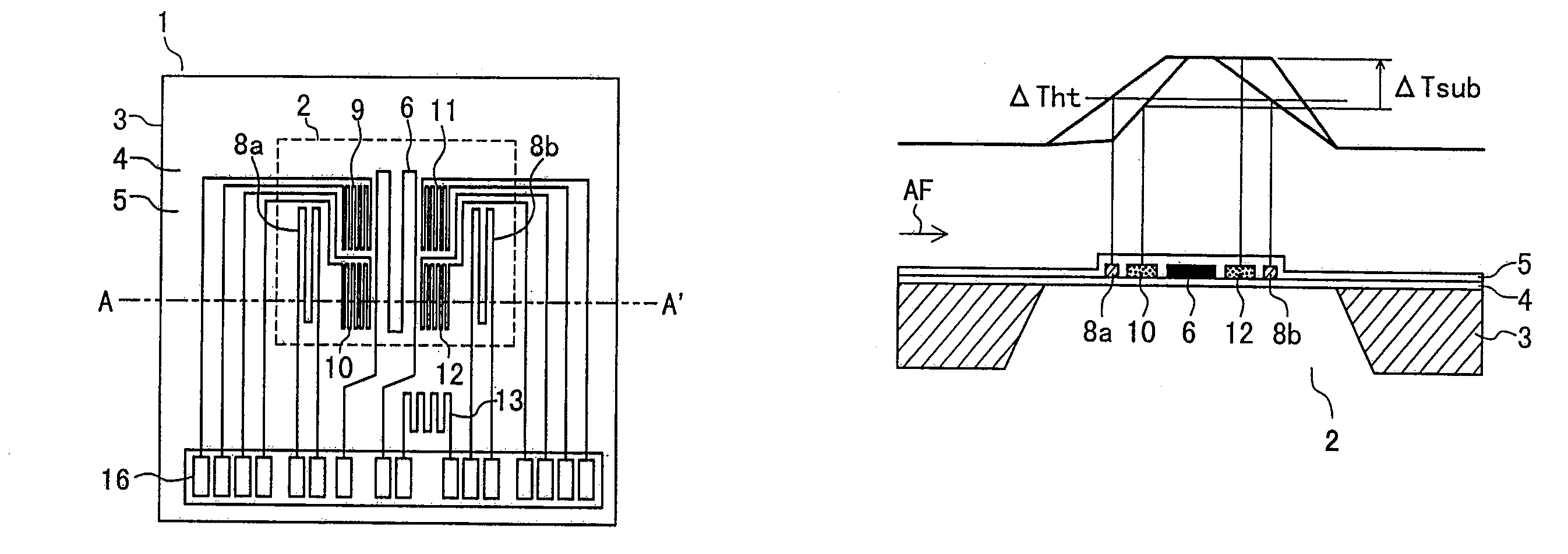
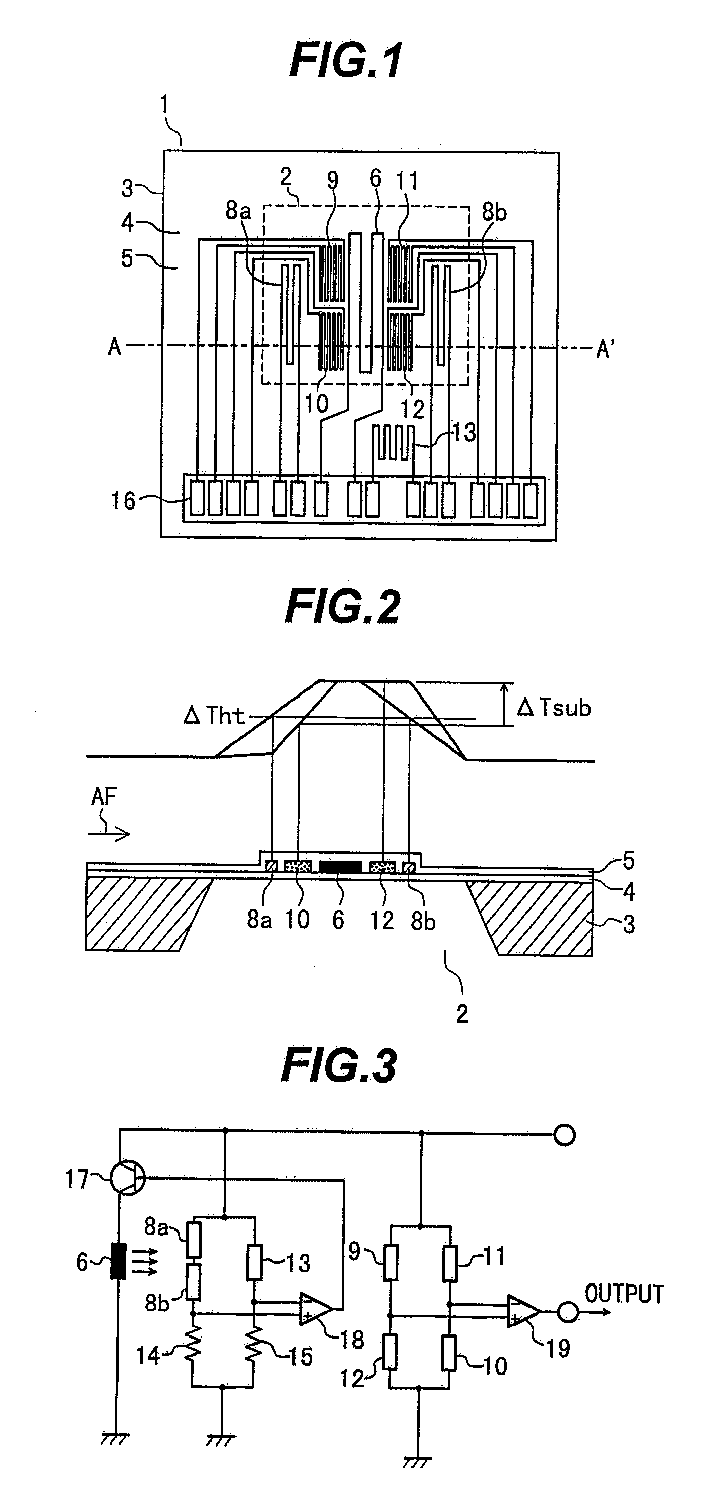
[0033]FIG. 1 is a plan view of a sensor device 1 of the thermal flowmeter according to the first embodiment of the present invention. FIG. 2 depicts a cross-section along the line A-A′ in FIG. 1 and shows temperature distributions across a diaphragm part 2.

[0034]In FIG. 1 and FIG. 2, the substrate 3 of the sensor device 1 is made of silicon, ceramic or other higher heat conductive materials. An insulation film 4 is formed on the substrate 3, and then the substrate 3 is etched from its back side so as to form the diaphragm part 2 under the insulation film 4.

[0035]On the surface of the diaphragm part 2, a heater resistor 6 is formed. This heater resistor 6 is heated so that its temperature is higher than that of an air stream AF (fluid flow to be measured) by a certain degree. In addition, temperature difference sensors 9, 10, 11 and 12, which ...

second embodiment

[0063]The following describes the present invention.

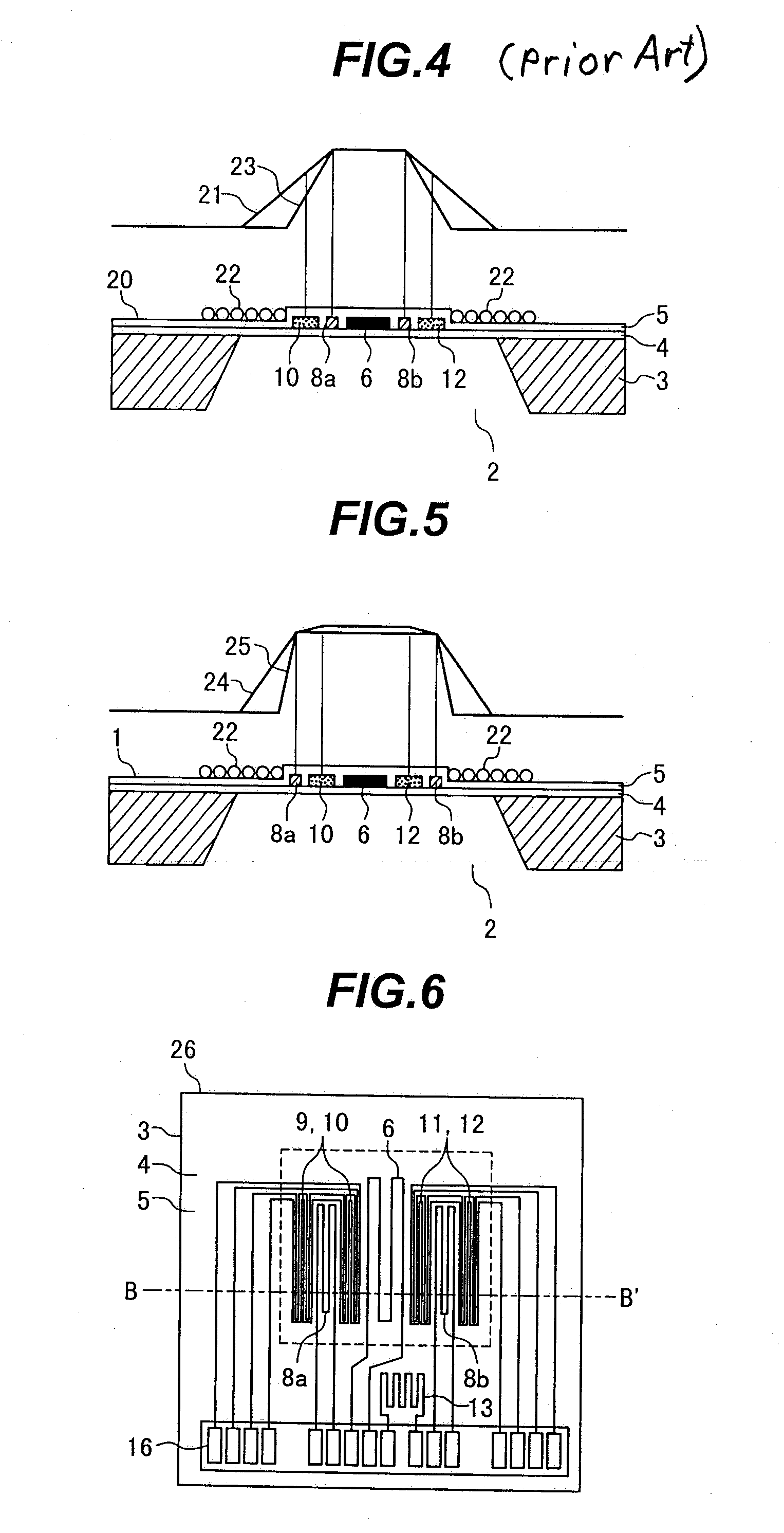
[0064]FIG. 6 is a plan view of a sensor device 26 in the second embodiment of the present invention. FIG. 7 depicts a cross-section along the line B-B′ in FIG. 6.

[0065]What differentiates the thermal flowmeter according to the second embodiment of the present invention from that of the first embodiment is the arrangement of the heating temperature sensors 8a and 8b and temperature difference sensors 9, 10, 11 and 12. The drive / detect method for and with the sensor device 26 is the same as in the first embodiment. The following describes what is different from the first embodiment.

[0066]In FIG. 6 and FIG. 7, the temperature difference sensors 9 and 10 are patterned upstream of the heater resistor 6 so that they are disposed respectively upstream and downstream of the upstream heating temperature sensor 8a. That is, the upstream heating temperature sensor 8a is sandwiched between the upstream temperature difference sensors 9 and 10.

[...

third embodiment

[0070]The following describes the present invention.

[0071]FIG. 8 depicts a cross-section of the diaphragm of a sensor device 27 in the third embodiment of the present invention. What differentiates the thermal flowmeter according to the third embodiment of the present invention from that of the second embodiment is the arrangement of the heating temperature sensors 8a and 8b and temperature difference sensors 9, 10, 11 and 12 in the sensor device 26. The drive / detect method for and with the sensor device is the same as in the first embodiment. The following describes what is different from the first embodiment.

[0072]Viewed from the top of the sensor device 27 shown in FIG. 8, the heating temperature sensors 8a and 8b are disposed on the temperature difference sensors 9, 10, 11 and 12 via the insulation film 5. That is, viewed from the top of the sensor device 27, the upstream heating temperature sensor 8a overlaps with the upstream temperature difference sensors 9 and 10 while the d...


PUM


Abstract

A simply configured thermal flowmeter can provide high measurement accuracy over a long period of time by suppressing the characteristics degradation due to adhering contaminants. On the surface of a diaphragm part, a heater resistor is formed. Temperature difference sensors through are disposed on the two sides of the heater resistor (upstream and downstream sides in the flow direction of an air stream). The temperature difference sensors are disposed upstream of the heater resistor while the temperature difference sensors are disposed downstream of the heater resistor. Outside the temperature difference sensors, heating temperature sensors are formed. Control is performed so that the temperature of the heating temperature sensors is set higher than the air stream temperature by a certain degree. Therefore, even if contaminants adhere to the sensor device, the temperature of the heating temperature sensors is held constant. Since the temperature difference sensors to detect the flow rate is located between the heating temperature sensors, the temperature change due to the contamination is small. This suppresses the characteristics degradation, making it possible to provide high measurement accuracy over a long period of time.

Description

BACKGROUND OF THE INVENTION[0001]1. Field of the Invention[0002]The present invention relates to a thermal flowmeter having heater resistors formed on a substrate for specific flow measurement.[0003]2. Description of the Related Art[0004]For example, as a flow sensor to detect the amount of air taken into an automobile internal combustion engine, it has become common to use a thermal air flow sensor capable of directly measuring the mass flow.[0005]The recently proposed thermal flowmeters include those characterized in that sensor elements are formed on a semiconductor substrate of silicon (Si) or the like by micromachining technology. In such a semiconductor type thermal flowmeter, a heater resistor is fabricated on a several-micron film formed on the semiconductor substrate. Due to the thinness, its thermal capacity is small enough to allow high speed response and low power drive.[0006]In addition, this type of thermal flowmeter makes it easier to form a fine structure for detecti...

Claims


Application Information

Patent Timeline
Patent Type & Authority Patents(United States)
IPC IPC(8): G01F1/68
CPCG01F1/6845G01F1/692G01F1/699
Inventor NAKANO, HIROSHIMATSUMOTO, MASAHIROHANZAWA, KEIJI
Owner HITACHI ASTEMO LTD
Why Eureka
Try Eureka