
Broach tool and a broach insert

a broach tool and insert technology, applied in the direction of broaching tools, rectilinear broaching, broaching machines, etc., can solve the problems of difficulty in replacing worn broach inserts, difficulty in dismantling entire broach tools, and difficulty in removing entire broach tools, etc., to achieve easy replacement and good precision

Inactive Publication Date: 2011-12-06
SECO TOOLS AB
View PDF13 Cites 5 Cited by
  • Summary
  • Abstract
  • Description
  • Claims
  • Application Information

AI Technical Summary

Benefits of technology

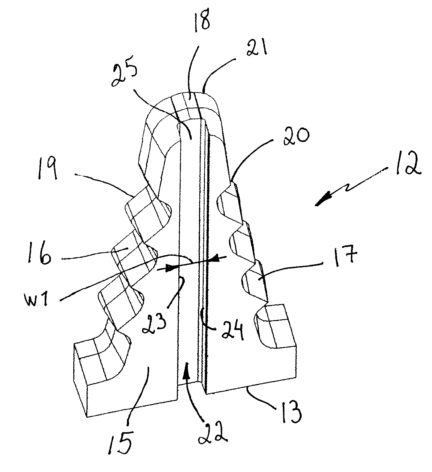
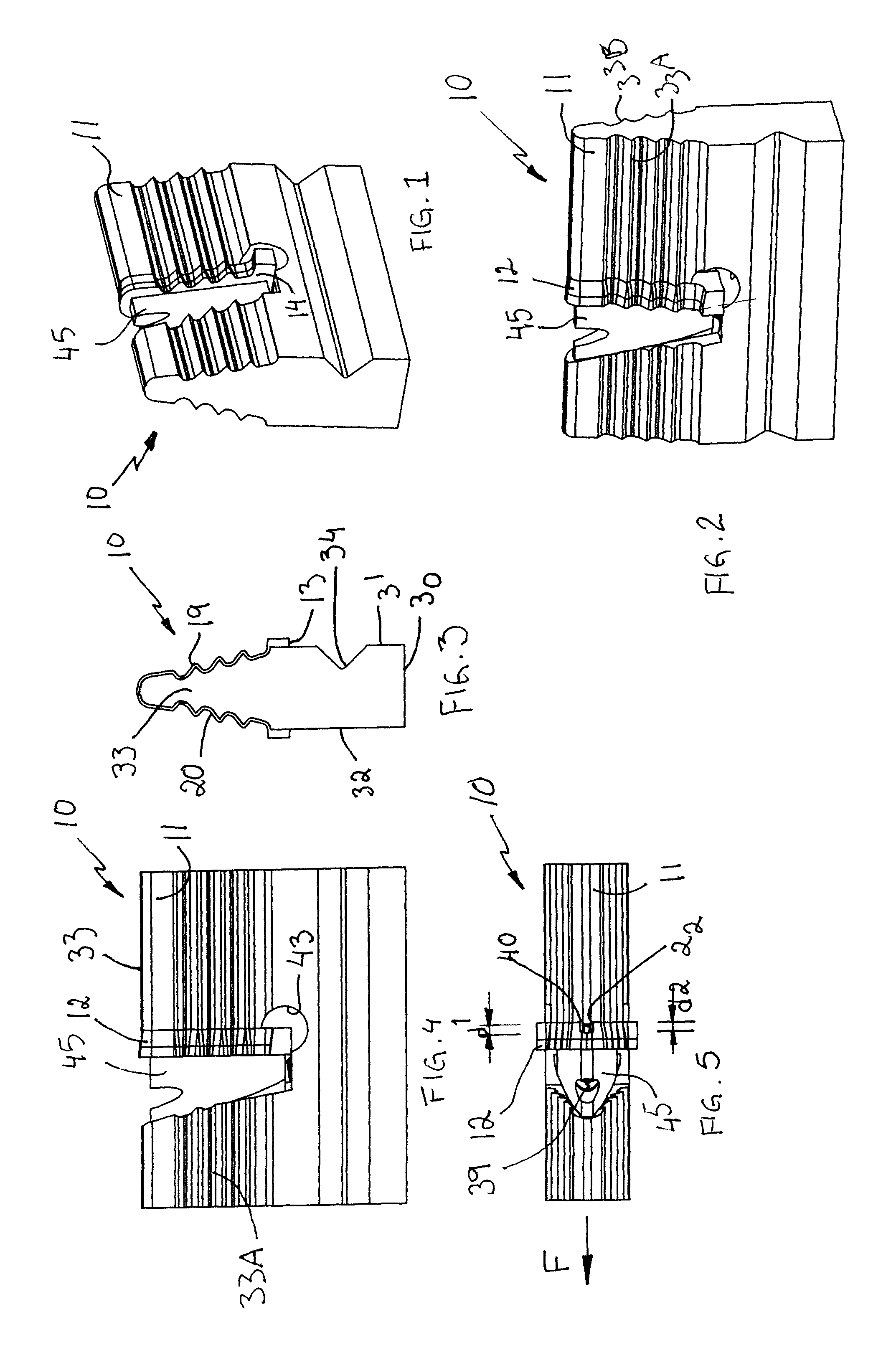
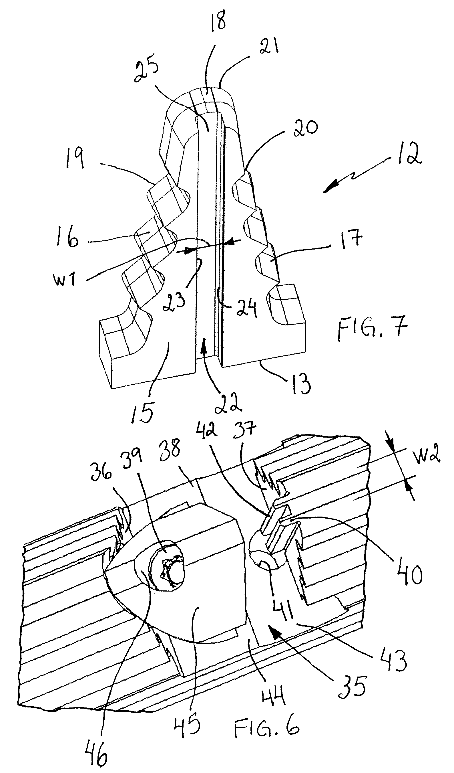
The present invention relates to a new broach tool and broach insert for chip removing machining of metals. The new tool has the advantage of easy replacement of worn broach inserts, stable use, good precision, and savings for the user. The tool comprises a holder with at least one recess for the cutting unit, which is a replaceable broach insert with a base part and cutting part. The cutting part has waved cutting edges. The holder has a clamping member in front of each cutting unit, which is elastically deformed by a notch formed centrally in the rear side surface of the broach insert. This new tool and insert design offer improved performance and efficiency in chip removing machining of metals.

Problems solved by technology

Conventional broach tools have the disadvantage that the replaceability of worn broach inserts has been problematic.
Furthermore, in other cases, damage to a cutting edge or some part of the tool has frequently resulted in the entire broach tool having been discarded or in a need of dismantling the entire broach tool.
The material from which a unitary broach tool is manufactured has usually been restricted to high-speed steels because of the relatively high cost associated with materials such as cemented carbide.

Method used


Image

  • Broach tool and a broach insert
  • Broach tool and a broach insert
  • Broach tool and a broach insert

Examples


Embodiment Construction

[0017]With reference to the figures, a broach tool 10 is shown comprising a holder 11 of broach inserts 12 according to the present invention. The holder 11 is designed and constructed to receive and safely hold at least one broach insert 12 during a reaming operation. The broach insert 12 is configured for reaming and is formed of a material appropriate for the desired reaming operation, such as preferably coated cemented carbide or high-speed steel, tool steel, or other hard metallic material. With “cemented carbide” is here meant WC, TiC, TaC, NbC, etc., in sintered combination with a binder metal such as for example Co or Ni. The cutting insert is preferably at least partly coated with at least a layer of for example Al2O3, TiN and / or TiCN. In some cases it can be well-founded that the cutting edges are made of brazed on super hard material such as CBN or PCD. The broach insert 12 has a generally triangular basic shape and comprises a base surface 13, a front side surface 14, a ...


PUM

PropertyMeasurementUnit
angleaaaaaaaaaa
widthaaaaaaaaaa
lengthaaaaaaaaaa

Abstract

A broach tool and a broach insert for chip removing machining of metals are provided. The broach tool includes an elongate holder and at least one cutting unit. The holder comprises at least one recess for the receipt of the cutting unit. The broach tool has a feeding direction. The broach tool includes clamping members for each cutting unit. Each clamping member is arranged in front of the cutting unit in the feeding direction. The cutting unit is a replaceable broach insert including a base part and a cutting part. A notch is formed centrally in a rear side surface of the broach insert. The recess includes a rear wall formed with a projection, the cross section of which is U-shaped and includes arms. The arms are arranged to be elastically deformed by the notch.

Description

BACKGROUND AND SUMMARY[0001]The present invention relates to a broach tool and a broach insert according to the preambles of the independent claims.[0002]Broach tools have been used for many years for the machining metallic materials. A conventional broach tool has a number of broach inserts threaded on a threaded rod and fixed by means of a nut. Conventional broach tools have the disadvantage that the replaceability of worn broach inserts has been problematic. Furthermore, in other cases, damage to a cutting edge or some part of the tool has frequently resulted in the entire broach tool having been discarded or in a need of dismantling the entire broach tool. The material from which a unitary broach tool is manufactured has usually been restricted to high-speed steels because of the relatively high cost associated with materials such as cemented carbide.[0003]Although many of the previously known broach tools, which have comprised broach inserts clamped into a tool body, have been ...

Claims


Application Information

Patent Timeline
Patent Type & Authority Patents(United States)
IPC IPC(8): B23P15/42B23D37/00
CPCB23D43/04Y10T407/16Y10T407/1628B23D2043/025B23D43/00
Inventor KOSKINEN, JORMABORGSTROM, JORGENAVDOVIC, PAJAZIT
Owner SECO TOOLS AB
Learn More