Embroidery using soluble thread

a technology of soluble thread and embroidery, applied in the field of embroidery using soluble thread, can solve the problems of unreliability, inability to repeat, and inability to achieve the effect of ensuring the quality of embroidery, increasing the cost of manufacturing, and high repeatability of lace within the embroidered structur

Active Publication Date: 2011-12-13
NUVASIVE
View PDF90 Cites 29 Cited by
  • Summary
  • Abstract
  • Description
  • Claims
  • Application Information

AI Technical Summary

Benefits of technology

[0014]According to the present invention, there is provided a manufacturing process by which an embroidered structure may be created containing within the structure one or more independent, unpaired threads laces, in a manner which is repeatable, inexpensive, and conducive to mass production.
[0015]The advantages to placing laces using the process of the present invention are: (1) ease of manufacture of complex devices; (2) the ability to make more complex devices; (3) the ability to improve the repeatability of strength critical items; (4) the ability to pre-load seams; and (5) the ability to create three-dimensional shapes.
[0019]Since the lace was a part of the embroidered structure as it was being created and not placed from outside the otherwise finished embroidered structure, and because the creation was performed non-manually, the positional repeatability of the lace within the embroidered structure is high. The replacement of standard threads with soluble threads and the addition of a process to remove the soluble thread, if not removed during a substrate dissolution process, only nominally increases the cost of manufacturing with laces as opposed to without, and the cost increase is significantly less that of the cost of placing laces by hand. Finally, since the method of creation may be automated using commercially available embroidery machines, the embroidered structures containing laces may be mass produced. Thus, the present invention overcomes, or at a minimum improves upon, the limitations associated with repeatability, expense, and mass producibility inherent to the prior art.

Problems solved by technology

The manual placement of laces is also expensive, not easily repeatable, and not conducive to mass production.
Repeatability is paramount in medical applications because devices may work reliably in one configuration, but variations of such a configuration may cause the device to perform unreliably, inadequately, or even fail to perform altogether.
Repeatability notwithstanding, the expense required to manually add one or more laces to embroidered structures further limits the use of manual insertion techniques, as does the bottleneck such manual insertions would cause in a manufacturing environment.

Method used


Image

  • Embroidery using soluble thread
  • Embroidery using soluble thread
  • Embroidery using soluble thread

Examples


first embodiment

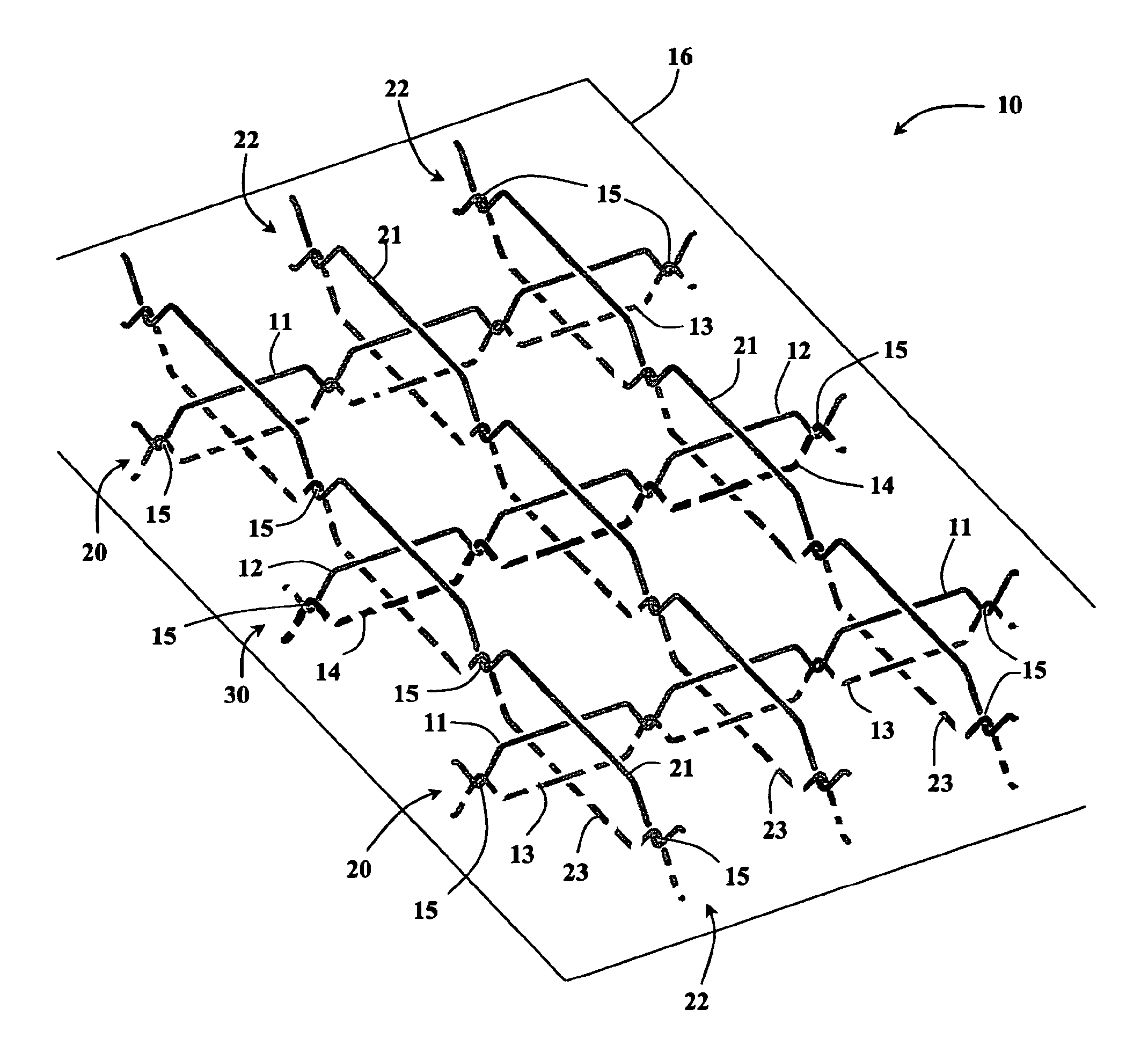
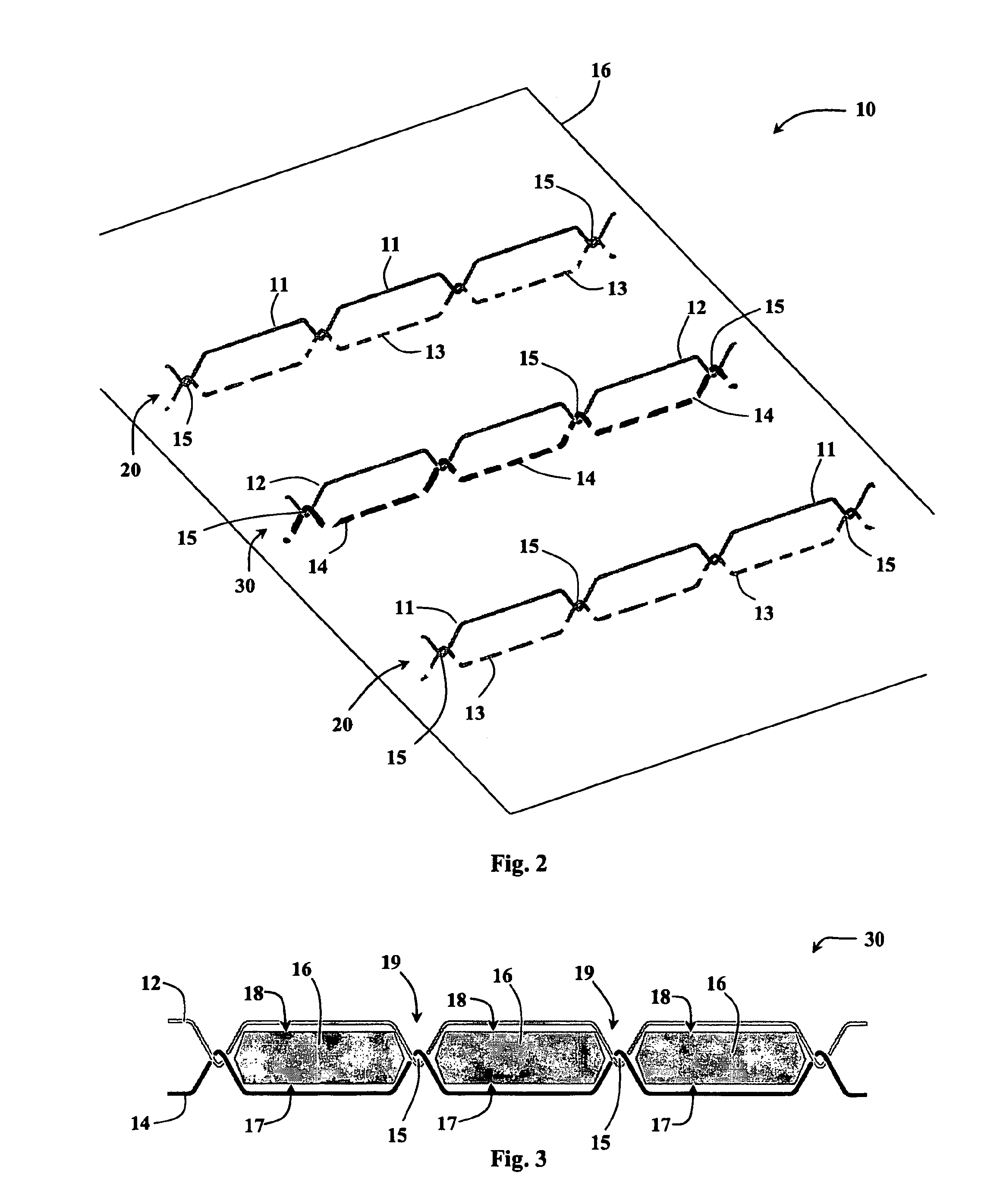
[0059]FIG. 6 depicts an example of an embroidered structure 40 according to the present invention. The embroidered structure 40 is shown by way of example as being generally flat, having a generally circular shape, and containing a series of laces 12 placed into the embroidery by the process of manufacture described above. The laces 12 are substituted for some of the stitching threads and soluble threads are substituted for the corresponding backing threads. The lace threads 12 and soluble threads are then stitched together forming temporary thread pairs while the remaining stitching threads and backing threads are stitched together forming a plurality of thread pairs 20. The thread pairs 20 and temporary thread pairs may then be enclosed by enclosing thread pairs 22 formed from enclosing stitching threads and enclosing backing threads. When the embroidering is completed, the soluble threads may be dissolved and the substrate may be removed. After dissolution of the soluble threads ...

second embodiment

[0061]FIG. 8 depicts an example of an embroidered structure 50 according to the present invention. The embroidered structure 50 is shown by way of example as being a generally flat, generally rectangular structure through which more than one lace 12 has been placed by the process of manufacture described above. The rectangular embroidered structure 50 necessarily has four edges; two shorter edges 52 and two longer edges 54. In this embodiment, the laces 12 run parallel to the two short edges 52 from one long edge 54 to the other long edge 54. Alternatively, the embroidered structure 50 could be arranged such that the laces 12 could run between short edges 54 parallel to the long edges 52, in which case the resulting cylindrical shape (see below) would be short and wide.

[0062]FIG. 9 illustrates the effect of tensioning and tying together the opposing ends of the laces 12 contained within the embroidered structure50 from FIG. 8. The laces 12 as laid out in the embroidered structure 50...

third embodiment

[0063]FIG. 10 depicts an example of an embroidered structure 60 according to the present invention. The embroidered structure 60 is shown by way of example as being a generally flat, generally rectangular structure through which a single lace 12 was placed multiple times by the process of manufacture described above. The generally rectangular embroidered structure 60 necessarily has four edges; two short edges 62 and two long edges 64. In this embodiment, the lace 12 runs generally diagonally from one long edge 64 to the other long edge 64, then around the outside of the embroidered structure 60 and back to the first long edge 64 where it enters the embroidered structure again. In an alternative embodiment, the lace 12 could be run between the short edges 62 to result in a differently dimensioned structure than the one described below.

[0064]As shown in FIG. 11, a three-dimensional, generally cylindrical embroidered structure 60 may be formed by tensioning the lace 12 of the embroide...


PUM


Abstract

A manufacturing process and resultant medical devices and components thereof wherein one or more individual laces (12) is placed within an embroidered structure (10) using an automated process allowing for the manufacture of embroidered surgical implants containing laces to be mass produced repeatably and cost effectively.

Description

CROSS-REFERENCES TO RELATED APPLICATIONS[0001]The present international patent application claims the benefit of priority from commonly owned and co-pending U.S. Provisional Patent Application Ser. No. 60 / 847,022, entitled “Embroidery Using Soluble Thread,” filed on Sep. 25, 2006, the entire contents of which are hereby expressly incorporated by reference into this disclosure as if set forth fully herein.BACKGROUND OF THE INVENTION[0002]I. Field of the Invention[0003]The present invention relates to medical devices and methods generally aimed at surgical implants. In particular, the disclosed system and associated methods are related to a manner of creating surgical implants via embroidery.[0004]II. Discussion of the Prior Art[0005]Embroidered structures are created on substrates. Some substrates are designed to stay in place with the embroidered structure while other substrates are removed at the end of the embroidery process. If the substrate is designed to be removed, the preferr...

Claims


Application Information

Patent Timeline
Patent Type & Authority Patents(United States)
IPC IPC(8): D05B93/00
CPCD05C7/00D05D2209/00
Inventor BUTCHER, PETERREAH, CHRISTOPHER
Owner NUVASIVE
Why Eureka
Try Eureka