Illumination apparatus, color conversion device, and display apparatus
a technology of color conversion device and display device, which is applied in the direction of lighting and heating apparatus, instruments, non-linear optics, etc., can solve the problems of poor light use efficiency and achieve the effects of improving luminance, excellent display quality, and less light loss
- Summary
- Abstract
- Description
- Claims
- Application Information
AI Technical Summary
Benefits of technology
Problems solved by technology
Method used
Image
Examples
first embodiment
[0062]Hereinafter, referring to FIGS. 1 to 7, an illumination apparatus according to an embodiment of the present invention will be described as a first embodiment.
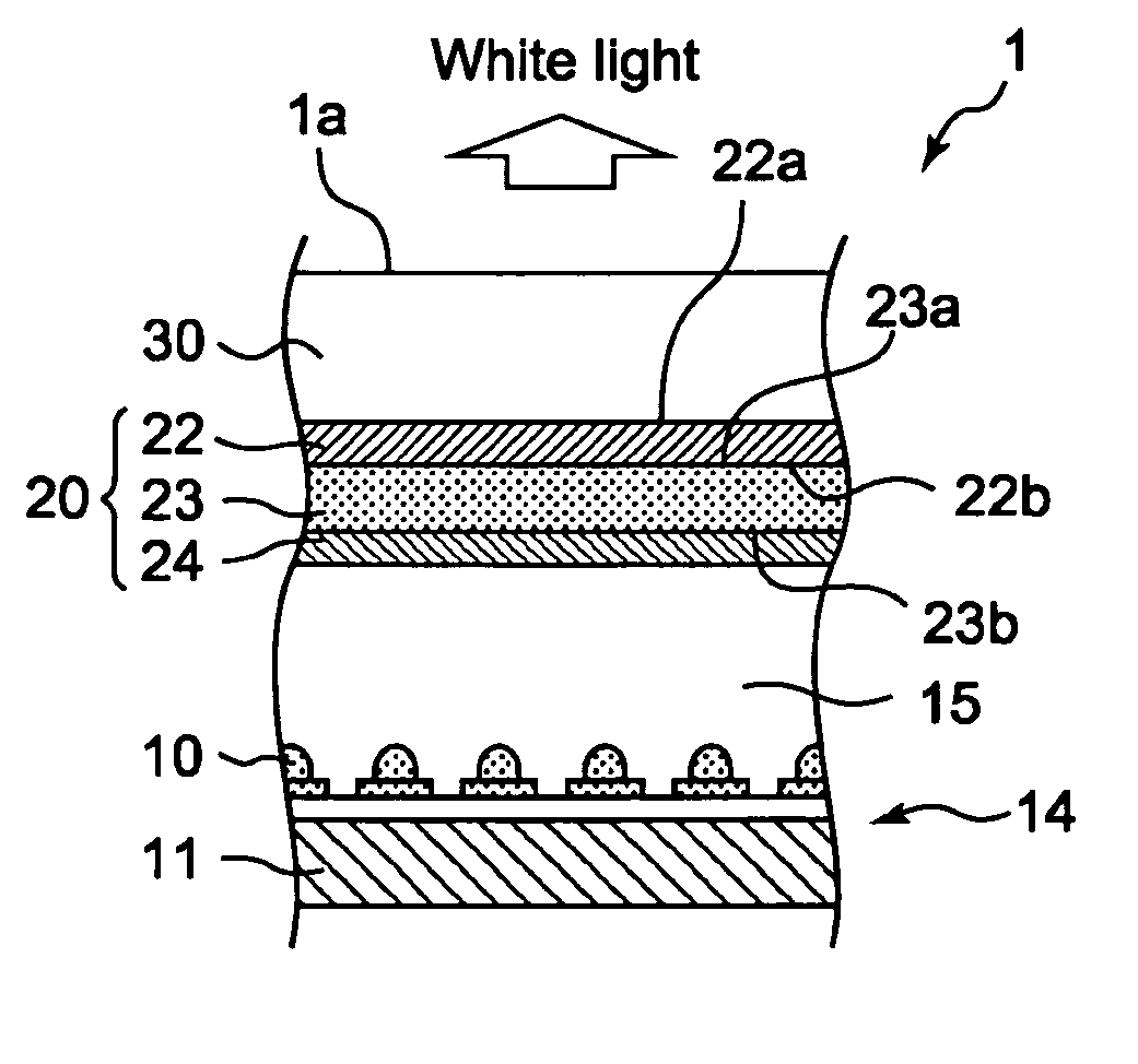
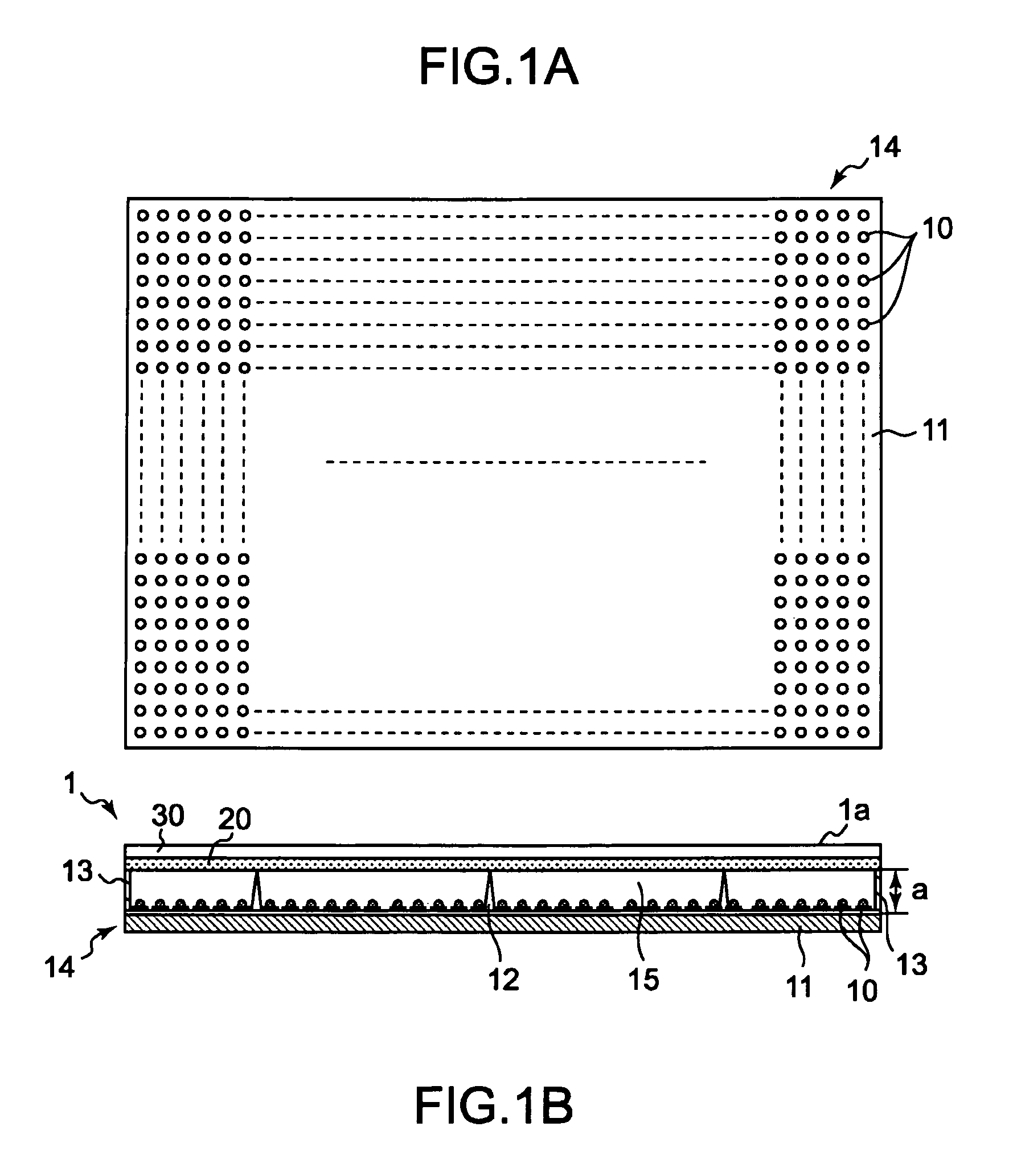
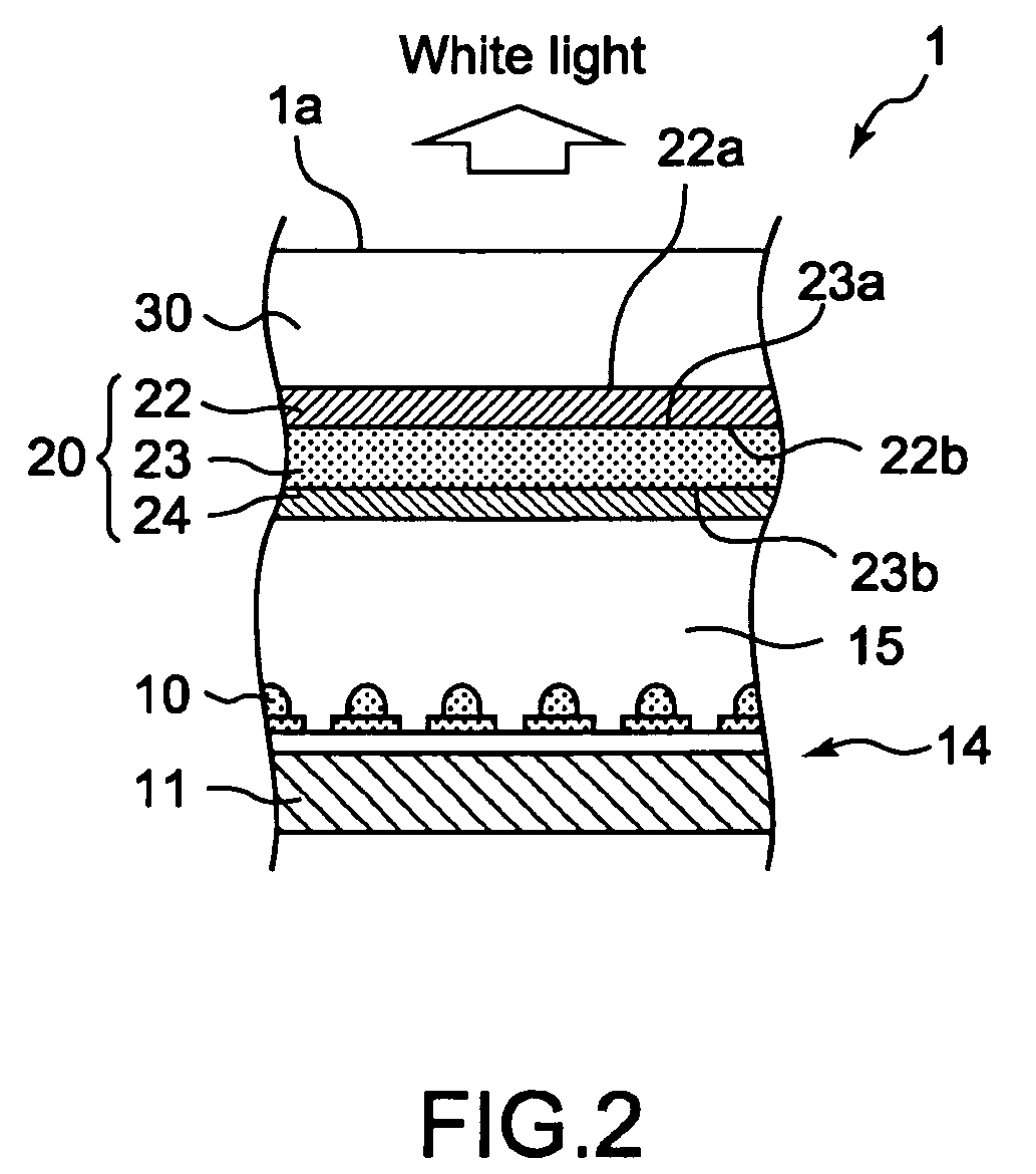
[0063]FIG. 1A is a schematic plan view of a light-emitting device substrate 14 partially constituting the illumination apparatus 1, and FIG. 1B is a schematic cross-sectional diagram of the illumination apparatus 1. FIG. 2 is a partially-enlarged cross-sectional diagram of the illumination apparatus 1. FIG. 3 is a diagram showing optical characteristics of a sheet-type color conversion device. FIG. 4 is a partially-enlarged cross-sectional diagram of a sheet-type color conversion device 20 partially constituting the illumination apparatus 1. FIG. 5 is a diagram showing an optical path of light in a case where an optical wavelength selection filter layer is not provided, and FIG. 6 is a diagram showing an optical path of light in a case where the optical wavelength selection filter layer is provided. FIGS. 7 and 8 are diag...
second embodiment
[0088]In the sheet-type color conversion device 20 of the first embodiment, although the phosphor layer 22 contains two types of phosphors, that is, the green-color phosphor and the red-color phosphor, phosphor layers may be disposed individually for each phosphor.
[0089]Hereinafter, descriptions will be given while referring to FIG. 9. FIG. 9 is a partially-enlarged cross-sectional diagram of a sheet-type color conversion device 120 according to a second embodiment of the present invention. Structures the same as those of the above embodiment are denoted by the same reference symbols, and descriptions thereof will be omitted.
[0090]As shown in FIG. 9, the sheet-type color conversion device 120 includes the transparent substrate 23 having the first surface 23a and the second surface 23b opposing each other, a first phosphor layer 122, a second optical wavelength selection filter layer 224, and a second phosphor layer 222 disposed on the first surface 23a of the transparent substrate 2...
third embodiment
[0095]FIG. 10 is a partially-enlarged cross-sectional diagram of a sheet-type color conversion device according to a third embodiment of the present invention. It should be noted that in FIG. 10, an illustration of the optical wavelength selection filter layer 24 is omitted. FIG. 11 shows optical characteristics of the sheet-type color conversion device of this embodiment.
[0096]As shown in FIG. 10, the sheet-type color conversion device of this embodiment includes, in addition to the structure of the sheet-type color conversion device 20 of the first embodiment, an antireflection layer 60 on the first surface 22a side of the phosphor layer 22. It should be noted that when providing the sheet-type color conversion device 120 of the second embodiment, the antireflection layer only needs to be disposed on the first surface 222a side of the second phosphor layer 222.
[0097]The antireflection layer 60 is provided for improving a light extraction efficiency of light from the phosphor layer...
PUM
 Abstract
Description
Claims
Application Information
 - R&D
- Intellectual Property
- Life Sciences
- Materials
- Tech Scout
- Unparalleled Data Quality
- Higher Quality Content
- 60% Fewer Hallucinations
Browse by: Latest US Patents, China's latest patents, Technical Efficacy Thesaurus, Application Domain, Technology Topic, Popular Technical Reports.
© 2025 PatSnap. All rights reserved.Legal|Privacy policy|Modern Slavery Act Transparency Statement|Sitemap|About US| Contact US: help@patsnap.com


