
Quantum dimming via sequential stepped modulation of LED arrays

a technology of led arrays and quantum dimming, which is applied in the direction of lighting and heating apparatus, process and machine control, instruments, etc., can solve the problems of reduced proportionality of leds, dimming of occupancy sensors in commercial establishments, and possible audible noise, so as to reduce the peak load of electronic components, efficiently utilize, and prolong the life of electronic components

Active Publication Date: 2011-12-13
LIGHT PRESCRIPTIONS INNOVATORS
View PDF13 Cites 65 Cited by
  • Summary
  • Abstract
  • Description
  • Claims
  • Application Information

AI Technical Summary

Benefits of technology

[0025]In one aspect, when one of the plurality of light sources malfunctions, the method may continue using only the remaining light sources. The cycle time may then be shortened, keeping the rate of switching events constant.
[0050]In one embodiment a sensor for chip over-temperature is included. LED performance is reduced at higher chip temperatures, and the LEDs may even fail. LEDs generate heat and the addition of high ambient temperature conditions may cause the LED to operate unsafely. To reduce the temperature of the light source if overheating is detected, automatic dimming is implemented. That reduces the heat generated by the LEDs and can lower the overall temperature of the light source to a sustainable level.

Problems solved by technology

Also, occupancy sensors in commercial establishments can run on dim when no customers are nearby.
As rheostat output voltage is reduced, the current through the LEDs is reduced in proportion, and at low enough levels the current through the LEDs will fall below their threshold level, which can damage them.
With the triac, the LEDs are off for part of each AC cycle, resulting in a perceptible flicker and possibly some audible noise.

Method used


Image

  • Quantum dimming via sequential stepped modulation of LED arrays
  • Quantum dimming via sequential stepped modulation of LED arrays
  • Quantum dimming via sequential stepped modulation of LED arrays

Examples


Embodiment Construction

[0073]A better understanding of various features and advantages of the present invention will be obtained by reference to the following detailed description of the invention and accompanying drawings, which set forth illustrative embodiments in which principles of the invention are utilized.

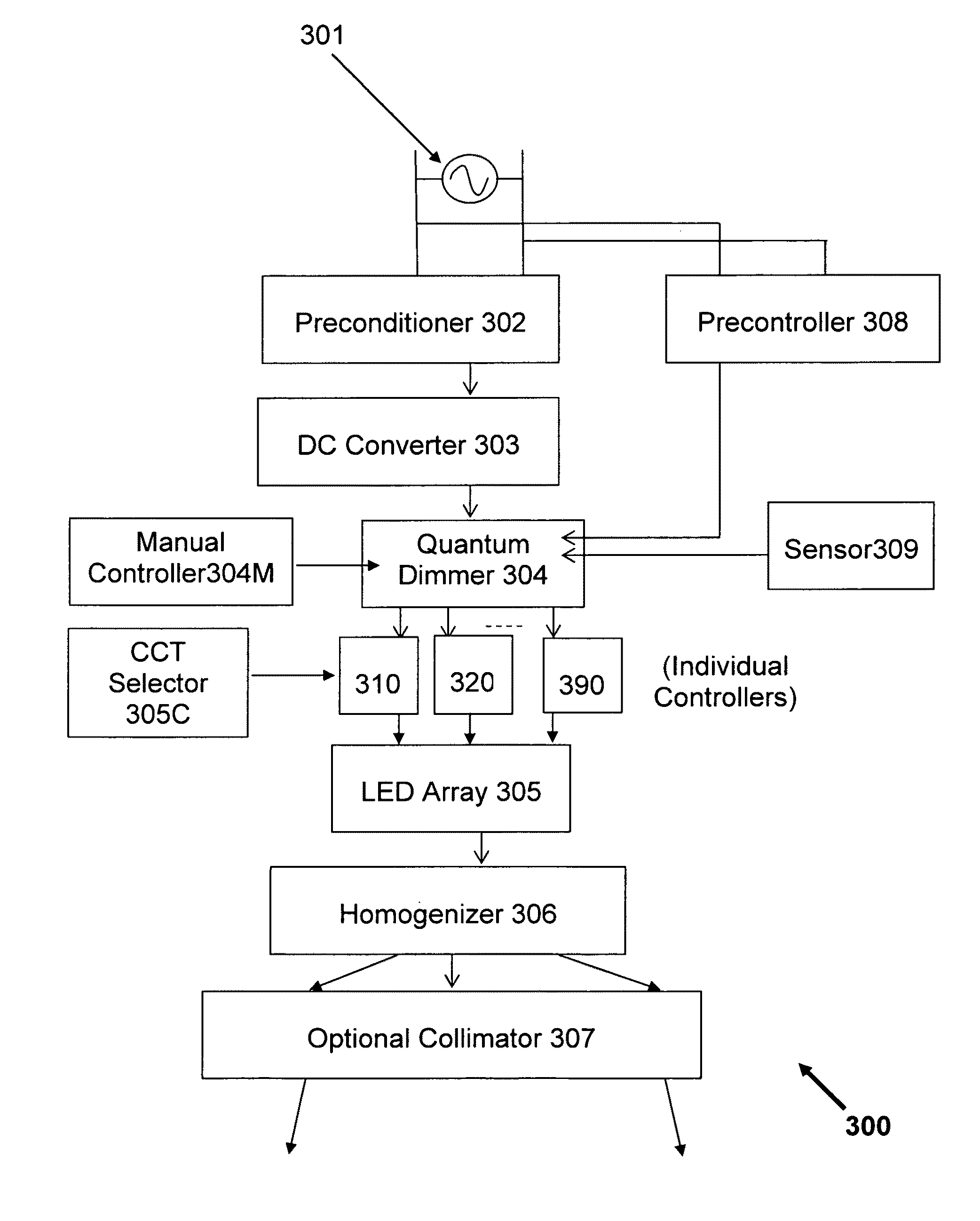
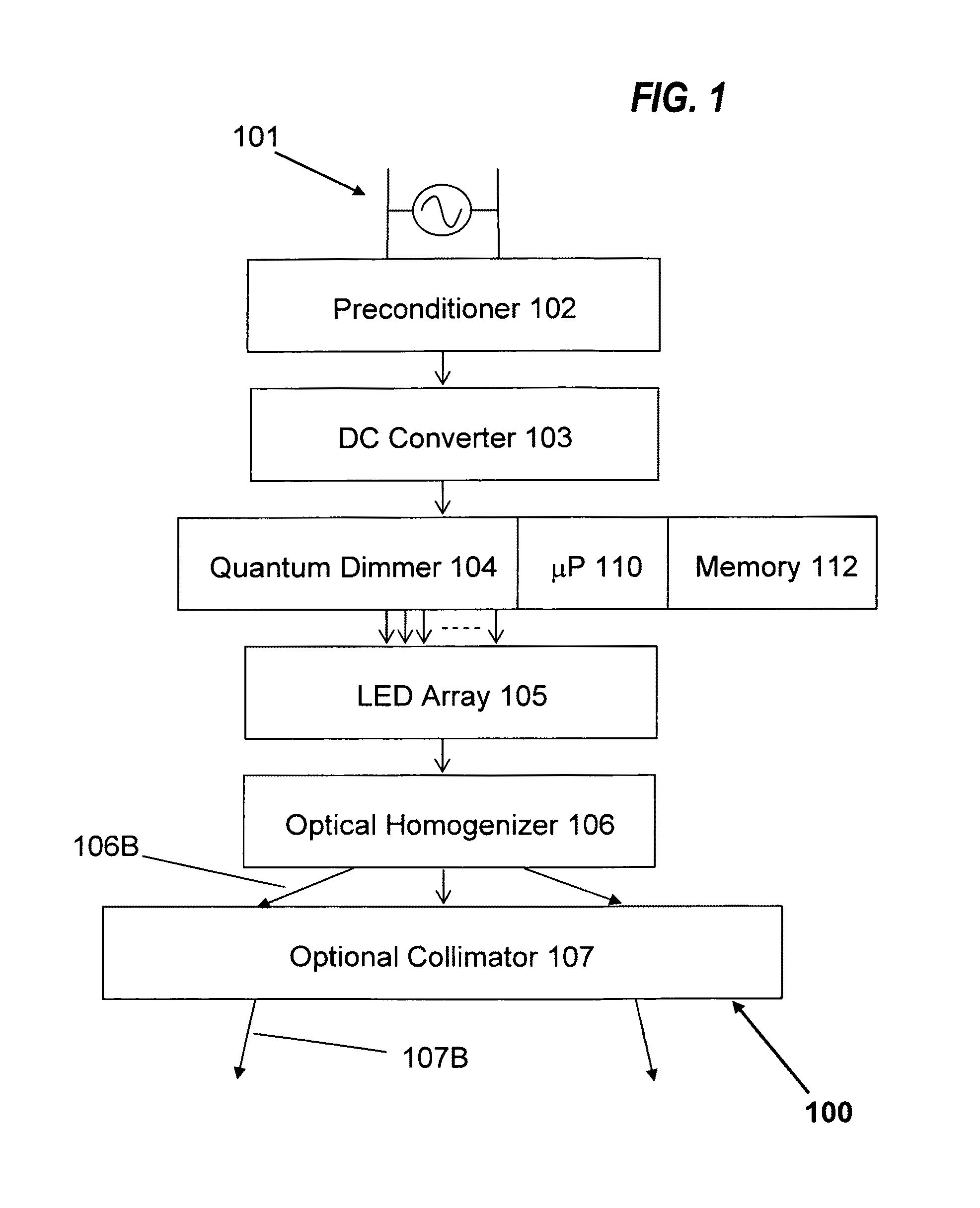
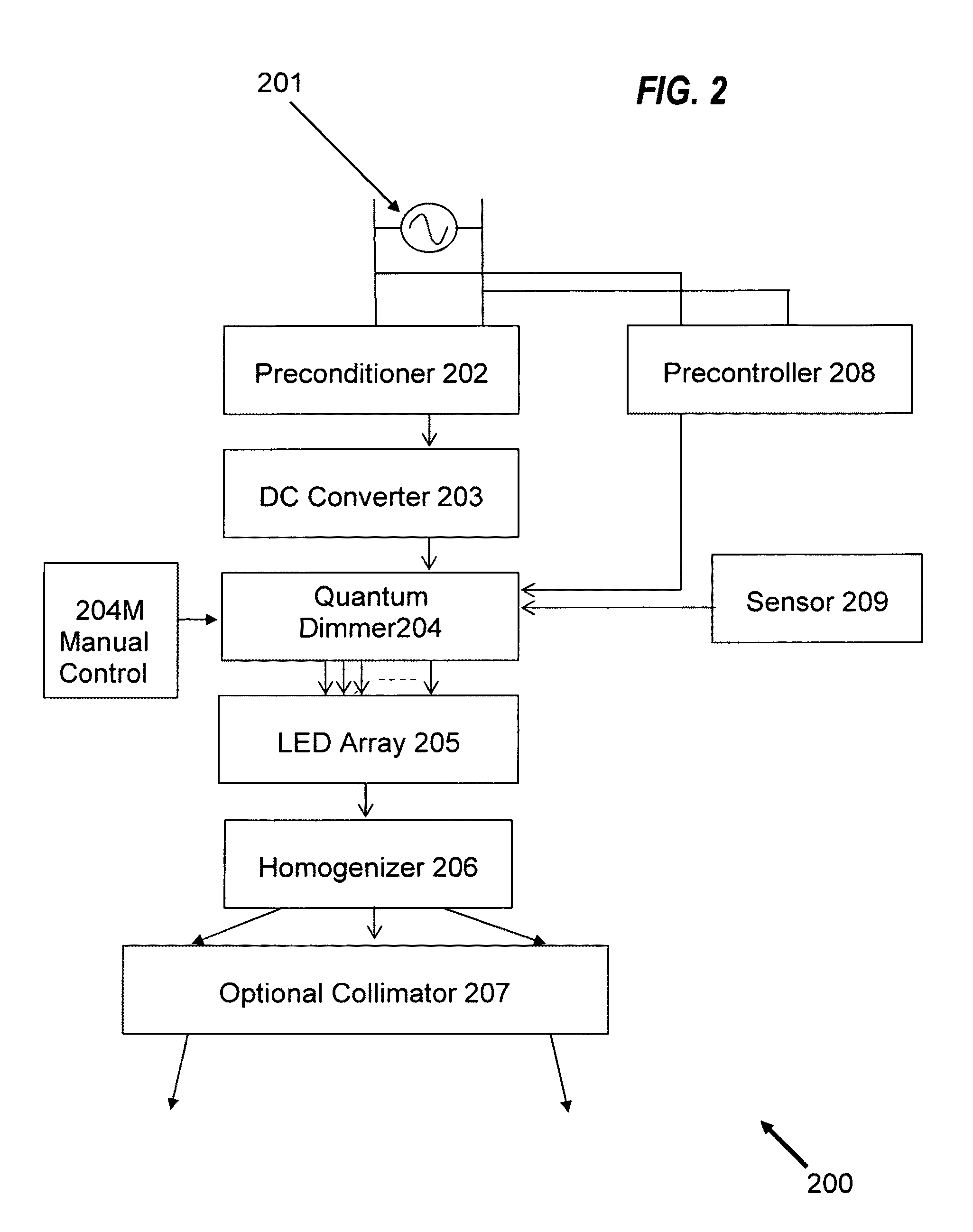
[0074]FIG. 1 shows an embodiment of a multi-LED illuminator, indicated generally by the reference number 100, comprising AC input line 101, pre-conditioner 102 for the incoming AC power from line 101, DC converter 103 receiving power from the pre-conditioner 102, quantum dimmer 104 supplied with power from the DC converter 103, LED array 105 driven by the quantum dimmer 104, optical homogenizer 106 homogenizing the light from all the LEDs in the array 105, and optional beam-forming collimator 107. AC input 101 may include a triac dimmer or other control that superimposes dimming commands on the incoming AC power. Such dimmer controls are well known and in the interests of conciseness are not furt...


PUM


Abstract

In one method of and apparatus for varying the luminosity of illumination, each of a plurality of light sources has an on state in which it emits light and an off state in which it does not emit light. Each of the plurality of light sources is switched cyclically between the on state and the off state in a sequence over a cycle period. The switching sequence is selected such that the number of said light sources that are on is uniform over the cycle. The luminosity of the illumination is varied by varying the proportion of each cycle for which each light source is switched on.

Description

CROSS REFERENCE TO RELATED APPLICATIONS[0001]This application claims benefit of U.S. Provisional Patent Application No. 61 / 106,524 titled “Dimmable LED Light Sources,” filed Oct. 17, 2008 in the name of Falicoff et al. and U.S. Provisional Patent Application No. 61 / 210,647 titled “Quantum Dimming via Sequential Stepped Modulation of LED Arrays,” filed Mar. 20, 2009 in the name of Shatford et al., both of which are incorporated herein by reference in their entirety.[0002]Reference is also made to:[0003]U.S. patent application Ser. No. 12 / 587,246 and International Patent Application No. PCT / US 2009 / 059495, both filed on Oct. 5, 2009, claiming priority from US Provisional Application No. 61 / 195,290 titled “Compact LED Downlight with Cuspated Flux-Redistribution Lens” filed on Oct. 6, 2008.[0004]U.S. patent application Ser. No. 12 / 456,392 and International Patent Application No. PCT / US 2009 / 003593, both filed on Jun. 15, 2009, titled “Multi-Reflector Cylindrical Light-Source with Interi...

Claims


Application Information

Patent Timeline
Patent Type & Authority Patents(United States)
IPC IPC(8): G05F1/00
CPCH05B33/0803H05B33/0815H05B33/0818H05B33/0863H05B33/0869Y02B20/346H05B45/56H05B45/20H05B45/37H05B45/22Y02B20/30H05B45/31H05B45/395
Inventor SHATFORD, WILLFALICOFF, WAQIDIPARKYN, WILLIAM A.SUN, YUPIN
Owner LIGHT PRESCRIPTIONS INNOVATORS
Learn More