Fastener driving apparatus

a technology for fasteners and driving apparatuses, which is applied in the direction of nailing tools, clutches, and fluid couplings, etc., can solve the problems of increased cost, increased weight of fastener driving apparatuses operated on compressed air, and increased cost of fuel cells, so as to reduce the cost of fuel consumption and reduce the speed of the drive. , the effect of preventing the consumption of drive energy

Active Publication Date: 2011-12-20
TRICORD SOLUTIONS
View PDF18 Cites 78 Cited by
  • Summary
  • Abstract
  • Description
  • Claims
  • Application Information

AI Technical Summary

Benefits of technology

[0010]Accordingly, an object of the present disclosure is to provide a fastener driving apparatus employing a retracting mechanism that precludes consumption of drive energy and reduction in drive speed of the fastener driving apparatus and facilitate a fastener to be fully driven into a workpiece.
[0011]Another object of the present disclosure is to provide a fastener driving apparatus that is portable in nature and is capable of providing more safety to a user.
[0012]Yet another object of the present disclosure is to provide a fastener driving apparatus that is capable of driving a fastener into a workpiece in a single stroke and is capable of increasing efficiency of the fastener driving apparatus.
[0013]Still another object of the present disclosure is to provide a fastener driving apparatus that is capable of minimizing reactionary force generated during fastener driving operation.
[0014]Still another object of the present disclosure is to provide a simplified fastener driving apparatus which is capable of being fabricated at a low manufacturing cost, permitting wide-scale adoption by the consumer.

Problems solved by technology

Although these fastener driving apparatuses are useful in driving the fasteners into the workpiece, such apparatuses have numerous limitations.
For example, the fastener driving apparatuses operated on the compressed air are bulkier, non-portable and costlier due to requirement of the air compressor and associated air-lines.
Fastener driving apparatuses operated on the fuel cells are complicated in design and are expensive.
Further, the apparatuses that are operated on the fuel cells require both electrical energy and fuel.
Further, the fastener driving apparatuses operated on the electrical energy are limited to fasteners of relatively small lengths, such as one inch or less.
Further, the fastener driving apparatuses operated on the electrical energy generate high reactionary force.
Further, the fastener driving apparatuses operated on the electrical energy are limited in their repetition rate because of long time it takes to drive a fastener into the work piece.
Moreover, although fastener driving apparatuses operated by flywheels are capable of driving the fasteners of longer sizes very quickly, these apparatuses are bulkier in sizes and weight.
Further, drive mechanisms of these apparatuses are complicated in design, which results in a high cost of such apparatuses.
Although such striker mechanisms are useful in driving the fasteners into the workpiece, these retracting mechanisms have numerous limitations.
For example, the retracting mechanisms, due to inertia associated therewith, consume significant drive energy of the fastener driving apparatuses and may prevent the fasteners from being fully driven into the workpiece.
Further, these retracting mechanisms reduce drive speed of the fastener driving apparatuses.
Furthermore, the existing retracting mechanisms may bias the striker mechanism towards the workpiece, causing a safety hazard for the user.

Method used


Image

  • Fastener driving apparatus
  • Fastener driving apparatus
  • Fastener driving apparatus

Examples


Embodiment Construction

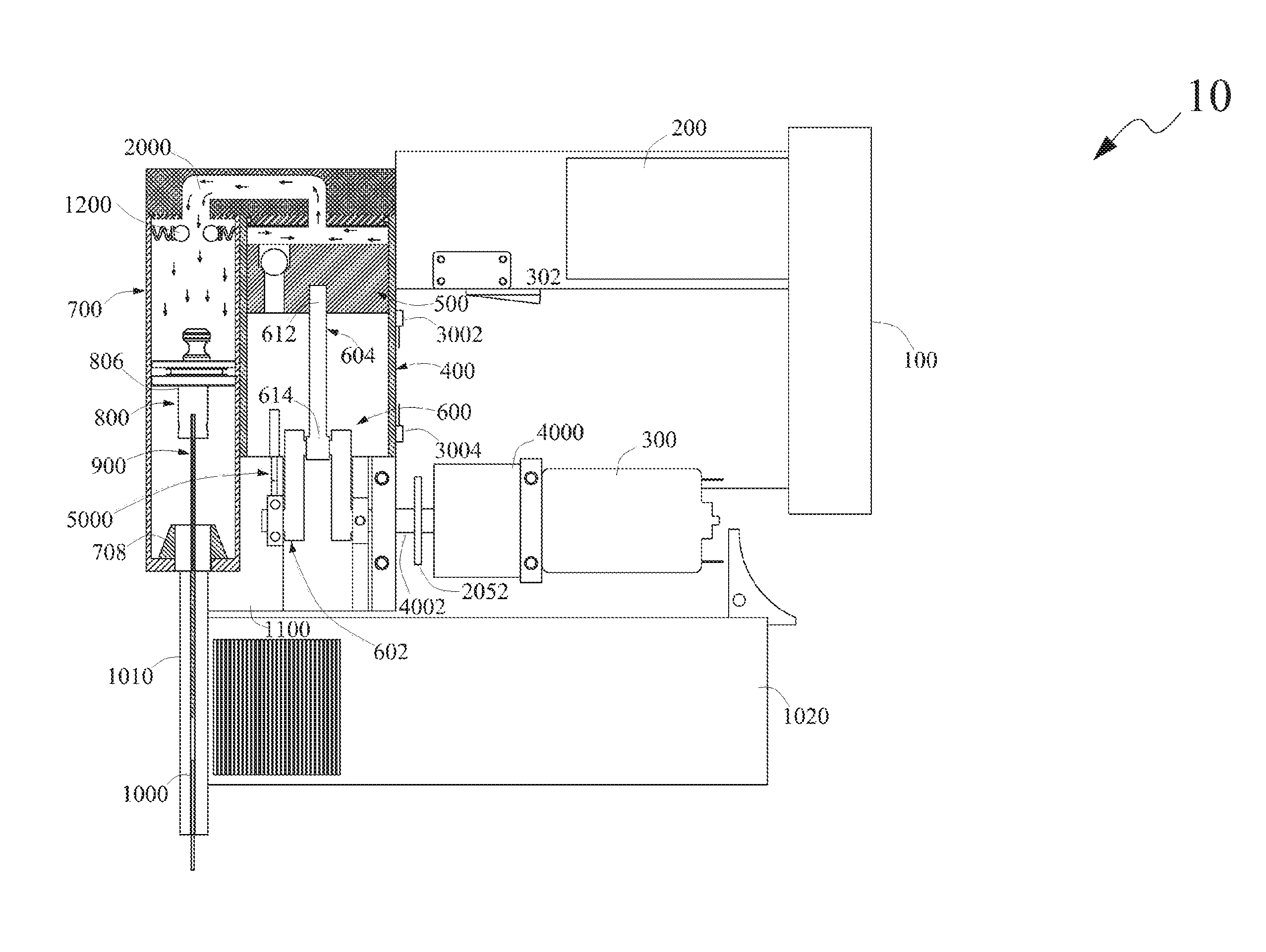
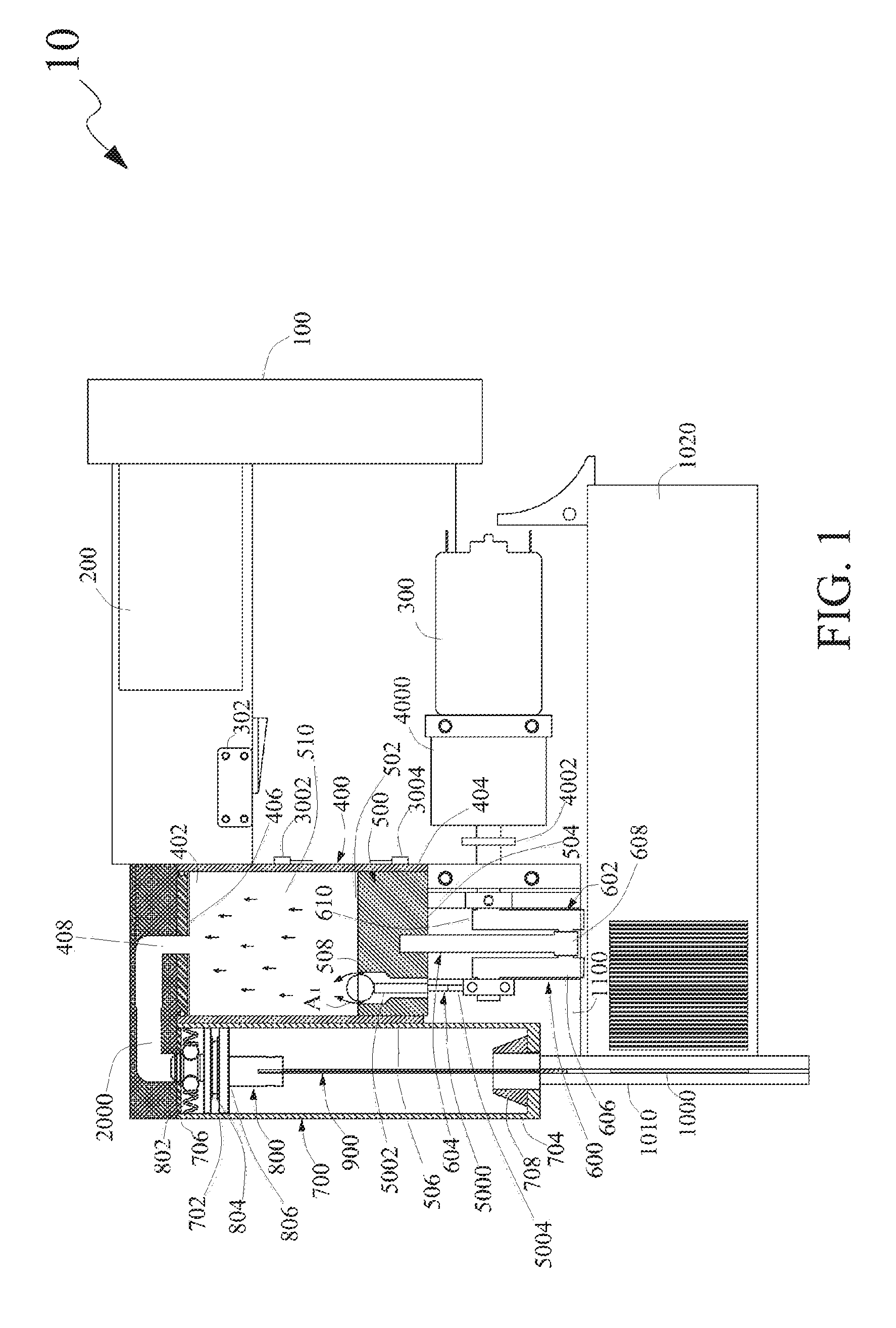
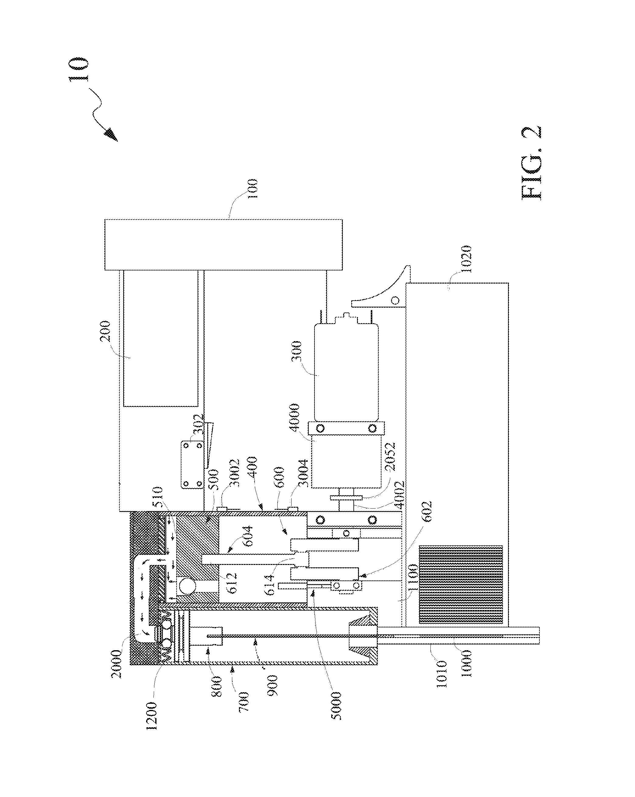
[0031]The exemplary embodiments described herein detail for illustrative purposes are subject to many variations in structure and design. It should be emphasized, however, that the present disclosure is not limited to a particular fastener driving apparatus as shown and described. It is understood that various omissions and substitutions of equivalents are contemplated as circumstances may suggest or render expedient, but these are intended to cover the application or implementation without departing from the spirit or scope of the claims of the present disclosure.

[0032]The terms “first,”“second,” and the like, herein do not denote any order, quantity, or importance, but rather are used to distinguish one element from another, and the terms “a” and “an” herein do not denote a limitation of quantity, but rather denote the presence of at least one of the referenced item.

[0033]The present disclosure provides a fastener driving apparatus for driving fasteners into a workpiece. As used h...


PUM

PropertyMeasurementUnit
lengthsaaaaaaaaaa
volumeaaaaaaaaaa
volumeaaaaaaaaaa

Abstract

A fastener driving apparatus includes a power source, a control circuit, a motor, a first cylinder, a first piston, a linear motion converter, a second cylinder, a second piston, an anvil, a retention element retaining a component of the apparatus, and at least one sensor. During a compression stroke, the first piston compresses gas in a first cylinder to a predetermined pressure. Compressed gas is communicated to the second cylinder and the retention force of the retention element is overcome, to release the retained component of the apparatus, thereby causing the second piston to move linearly and enabling the anvil to drive the fastener into the workpiece. During a return stroke of the first piston, a vacuum created in the first cylinder is communicated to the second cylinder, causing the second piston and the anvil to retract to their initial positions.

Description

CROSS REFERENCE TO RELATED APPLICATIONS[0001]The present disclosure claims priority under 35 United States Code, Section 119 on the U.S. Provisional Patent Application numbered 61 / 410,149 filed on Nov. 4, 2010, the disclosure of which is incorporated by reference.FIELD OF THE DISCLOSURE[0002]The present disclosure generally relates to apparatuses for driving fasteners into workpiece, and more particularly, to a fastener driving apparatus used as a portable hand tool.BACKGROUND OF THE DISCLOSURE[0003]A fastener driving apparatus is a tool used to drive fasteners, such as nails and staples into a workpiece. The fastener driving apparatus may be used for various operations, such as making wooden walls, positioning hang sheathings over the wooden walls, fastening baseboards over a lower portion of an interior wall and crown molding.[0004]There are various fastener driving apparatuses known in the art. These fastener driving apparatuses operate utilize various means and mechanisms known ...

Claims


Application Information

Patent Timeline
Patent Type & Authority Patents(United States)
IPC IPC(8): B25C1/04B25C1/06
CPCB25C1/04B25C1/06
Inventor PEDICINI, CHRISTOPHERWITZIGREUTER, JOHN
Owner TRICORD SOLUTIONS
Why Eureka
Try Eureka