System and method for providing chirped electromagnetic radiation

a technology of electromagnetic radiation and electromagnetic radiation, applied in the field of electromagnetic radiation sources, can solve the problems of inability to provide range and/or range rate information instantaneously, unambiguous distance determination, and conventional systems are typically limited in various aspects of operation, so as to enhance the coherence length of electromagnetic radiation, enhance the range, speed, accuracy, etc. of the laser radar system

Active Publication Date: 2011-12-20
AEVA INC
View PDF94 Cites 5 Cited by
  • Summary
  • Abstract
  • Description
  • Claims
  • Application Information

AI Technical Summary

Benefits of technology

[0009]One aspect of the invention may relate to a system and method for controllably chirping electromagnetic radiation from a radiation source. The system and method may include an optical cavity arrangement that enables electromagnetic radiation to be produced with a substantially linear chirp rate and a configurable period. By selectively injecting electromagnetic radiation into the optical cavity, the electromagnetic radiation may be produced with a single resonant mode that is frequency shifted at the substantially linear chirp rate. Producing the electromagnetic radiation with a single resonant mode may increase the coherence length of the electromagnetic radiation, which may be advantageous when the electromagnetic radiation is implemented in various applications. For example, the electromagnetic radiation produced by the optical cavity arrangement may enhance a range, speed, accuracy, and / or other aspects of a laser radar system.

Problems solved by technology

Conventional systems are typically limited in various aspects of operation.
For example, these conventional systems are not able to provide range and / or range rate information instantaneously based on the target signal and reference signal, or unambiguously determine distance and velocity.
These conventional systems are limited in other ways as well.
These limitations may be exacerbated by various operating conditions such as, for example, target acceleration toward or away from the target interferometer, using an actuated optical element (e.g. a mirror or lens) to scan the target at high speeds, or other operating conditions.
Systems utilizing such a configuration may suffer some or all of the drawbacks associated with single laser source systems, as well as other drawbacks unique to two laser source systems.
Additionally, conventional systems may not enable sufficient control over the frequency of emitted electromagnetic radiation to suitably manipulate the chirp rate of the radiation, may not be capable of chirping the frequency of emitted electromagnetic radiation in a sufficiently linear manner, or include other drawbacks.
For example, radiation output from the optical cavity to a device may constitute a loss.
Other losses may also be present, such as losses to imperfections in the optical elements, or other parasitic losses.
Cavity losses may also reduce the energy stored within the optical cavity and / or the power output from the optical cavity.
Since different parts of the mirror are moving at different velocities, different parts of the target beam experience different Doppler shifts, which may introduce errors into the range and or range rate measurements.

Method used


Image

  • System and method for providing chirped electromagnetic radiation
  • System and method for providing chirped electromagnetic radiation
  • System and method for providing chirped electromagnetic radiation

Examples


Embodiment Construction

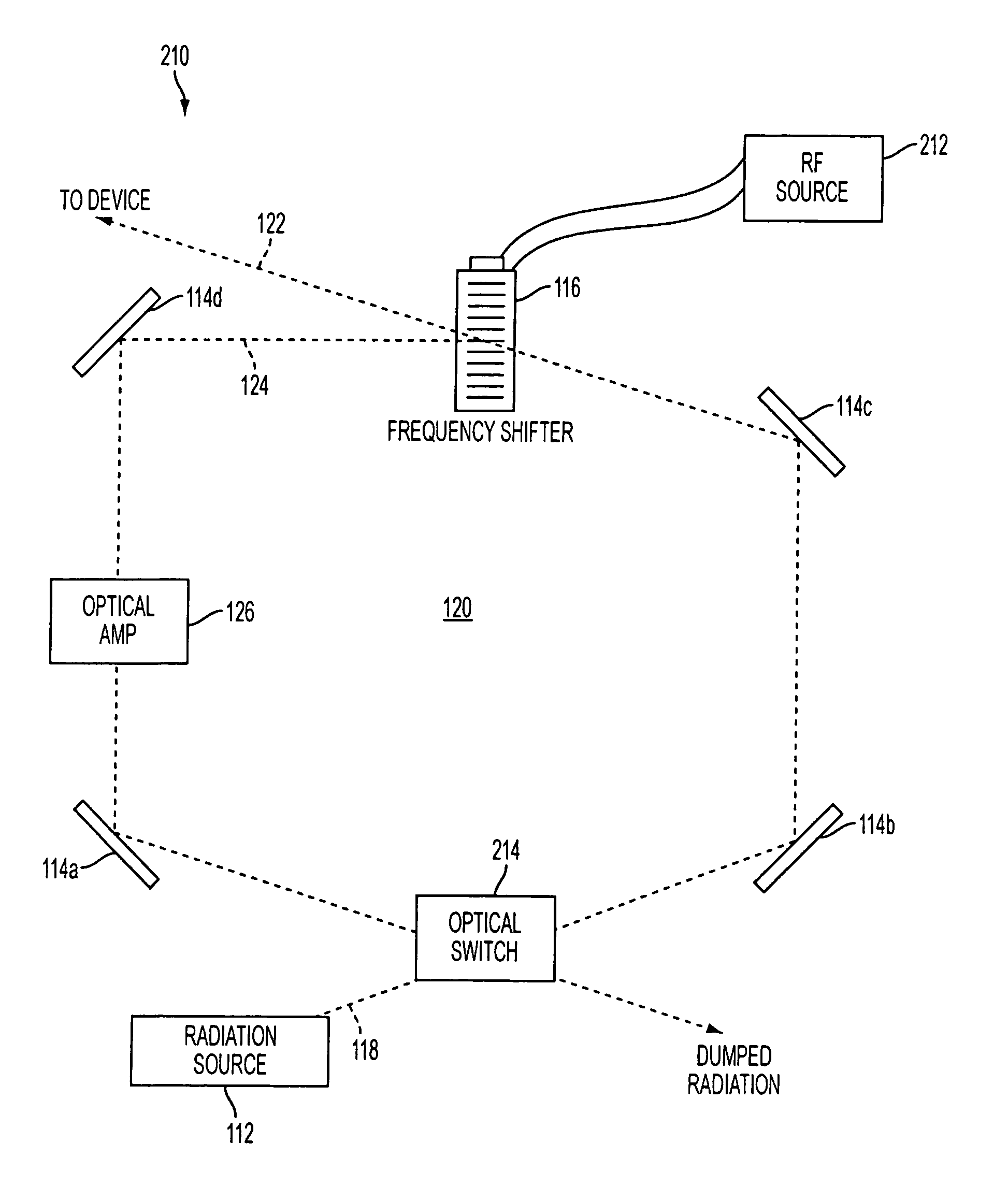
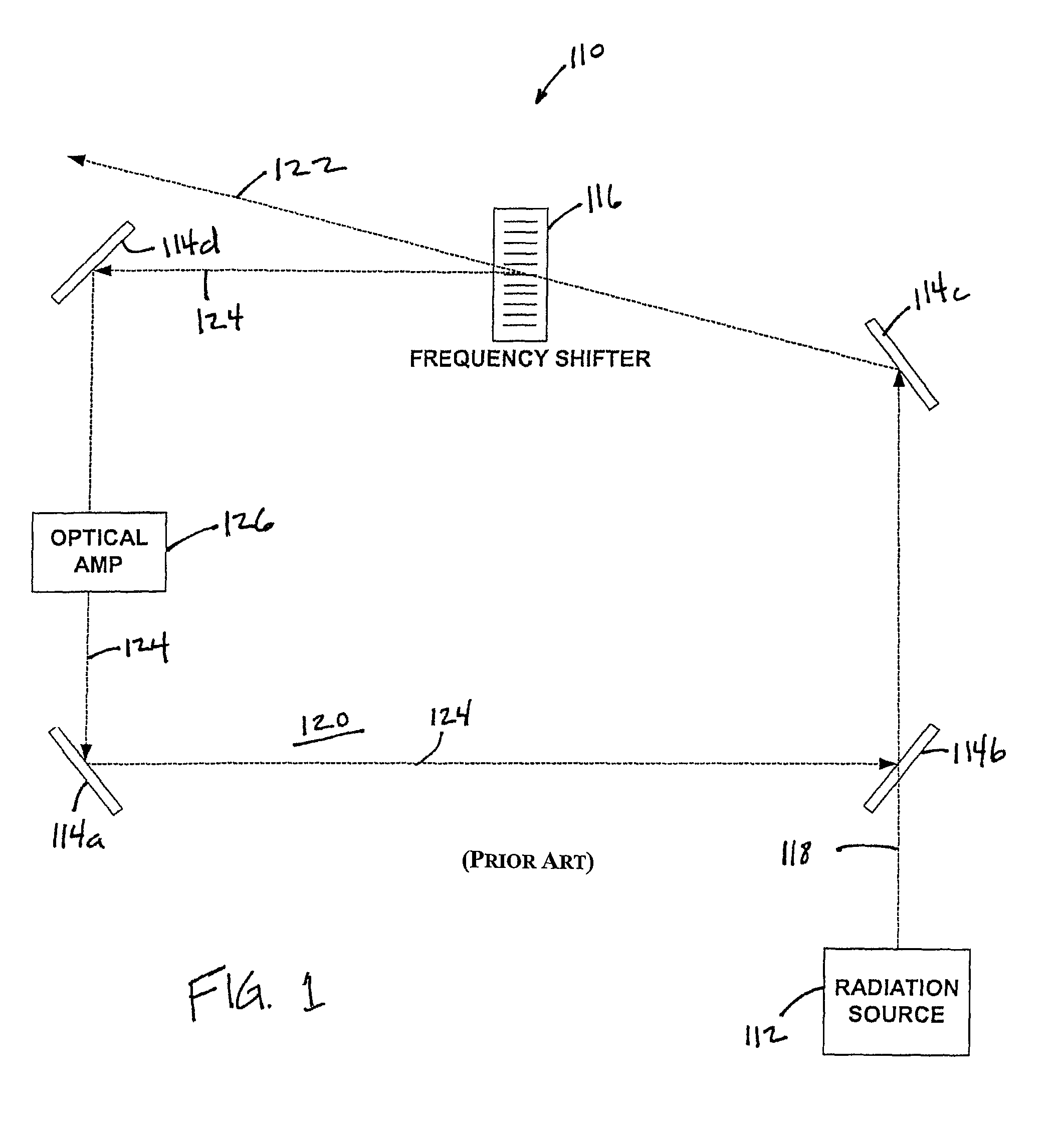
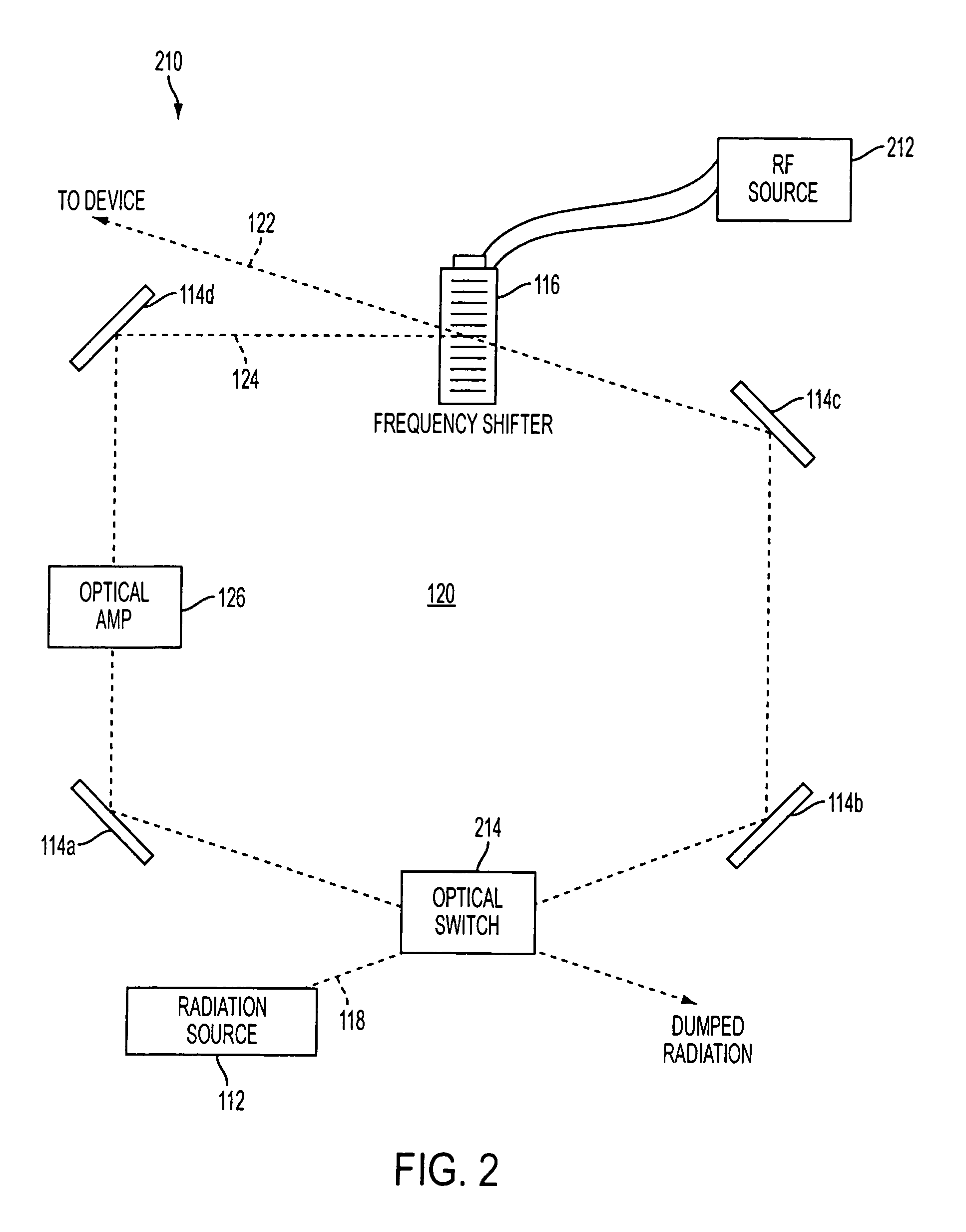
[0039]FIG. 1 illustrates a conventional system 110 for producing electromagnetic radiation at a frequency that is chirped at a substantially linear chirp rate. System 110 may include a radiation source 112, one or more optical elements 114 (illustrated as optical elements 114a-114d), and a frequency shifter 116. System 110 may be implemented to provide chirped electromagnetic radiation to a coherent laser radar device, a spectral analysis device, an interferometer, a remote sensing device, or another device.

[0040]In various conventional embodiments, radiation source 112 may provide a beam 118 of coherent electromagnetic radiation to system 110. Optical elements 114 may form an optical cavity 120, such as a ring cavity, for example. Beam 118 may be coupled to the optical cavity 120 to introduce the electromagnetic radiation that forms beam 118 into optical cavity 120. Frequency shifter 116 may be disposed in optical cavity 120 to receive the electromagnetic radiation, and may include...


PUM


Abstract

A system and method for controllably chirping electromagnetic radiation from a radiation source includes an optical cavity arrangement. The optical cavity arrangement enables electromagnetic radiation to be produced with a substantially linear chirp rate and a configurable period. By selectively injecting electromagnetic radiation into the optical cavity, the electromagnetic radiation may be produced with a single resonant mode that is frequency shifted at the substantially linear chirp rate. Producing the electromagnetic radiation with a single resonant mode may increase the coherence length of the electromagnetic radiation, which may be advantageous when the electromagnetic radiation is implemented in various applications. For example, the electromagnetic radiation produced by the optical cavity arrangement may enhance a range, speed, accuracy, and / or other aspects of a laser radar system.

Description

FIELD OF THE INVENTION[0001]The invention relates to electromagnetic radiation sources and more particularly to systems and methods for providing chirped electromagnetic radiation.BACKGROUND OF THE INVENTION[0002]Various measuring devices for measuring linear distances using one or more laser radars are known. Such measuring devices may generate information related to a distance or range of a target from the measuring device and / or a velocity, or range rate, of the target relative to the measuring device. This range and range rate information may be useful in a variety of settings. For the purposes of this application the term range rate refers to the rate of change in the range between the target and the measuring device.[0003]A typical measuring device may include, for example, a frequency modulated laser radar system. The system may include a laser source that emits a beam of electromagnetic radiation. The beam may be emitted at a frequency that is continuously varied, or chirped...

Claims


Application Information

Patent Timeline
Patent Type & Authority Patents(United States)
IPC IPC(8): H01S3/10G01S7/4911G01S17/26G01S17/34
CPCG01S7/484G01S17/102H01S3/0057G02F1/11G02F2203/15H01S3/235H01S3/1062H01S3/1103G02F2203/25G01S7/4911G01S17/34G01S17/26
Inventor BELSLEY, KENDALL
Owner AEVA INC
Why Eureka
Try Eureka