
Surgical fixation pin

a technology of fixation pin and pin, which is applied in the field of pin, can solve the problems of secondary displacement of fracture, wrist stiffness, and immobilization of wrist joints by traditional external fixation

Active Publication Date: 2011-12-27
SWEMAC INNOVATION
View PDF20 Cites 8 Cited by
  • Summary
  • Abstract
  • Description
  • Claims
  • Application Information

AI Technical Summary

Benefits of technology

"The present invention is a pin designed for fixation of fractures, particularly wrist fractures. The pin has an angled front section and a double bent extra cortical part with an anchor eye, and is made of spring material. The implant is introduced through the fracture line into the intramedullary canal of the main body of the fractured bone and stabilizes the fracture by serving as a support. The implant has a low profile and does not normally require removal, avoiding a second procedure. The form of the implant is adapted to the specific anatomy of the radius or ulna. The technical effects of the invention include improved stability, reduced risk of complications, and reduced duration of hospitalization."

Problems solved by technology

Fractures of the distal forearm (wrist fractures) are the most common of all fractures (annual incidence about 3,000 / 1,000,000 inhabitants in the industrialized world) and constitutes by it's abundance a major therapeutic problem.
For a large number of the intermediate complex fractures the choice of treatment is less obvious; while plate fixation may be a too extensive and expensive procedure bandage immobilization may be insufficient to hold fracture fragments in the desired position while the fracture heals.
Other therapeutic modalities also have their drawbacks: classic external fixation immobilizes the wrist joint during treatment and wrist stiffness may ensue.
To avoid that, the external fixation is often removed before the fracture is consolidated, which may lead to secondary displacement of the fracture.
The second bone of the forearm, the ulna, is notoriously difficult to fix, and fractures of the distal ulna are therefore often neglected.
It has been difficult to operate in such supports by the fracture area, and even more difficult to remove them.
The introduction of the pin in the bone has not been facilitated with similarly known pins, and neither has the screwing of them into the bone been proven to be easy to achieve.
It is difficult to insert pins in the bone, and sometimes a power drill is required.
It is also difficult to securely anchor the pin in the bone, which is why they frequently slide out.
In addition, they are frequently left protruding from the skin, with the risk of both inflammation around the pin as well as infection, which can spread to the bone and develop into osteomyelitis.

Method used


Image

  • Surgical fixation pin
  • Surgical fixation pin
  • Surgical fixation pin

Examples


Embodiment Construction

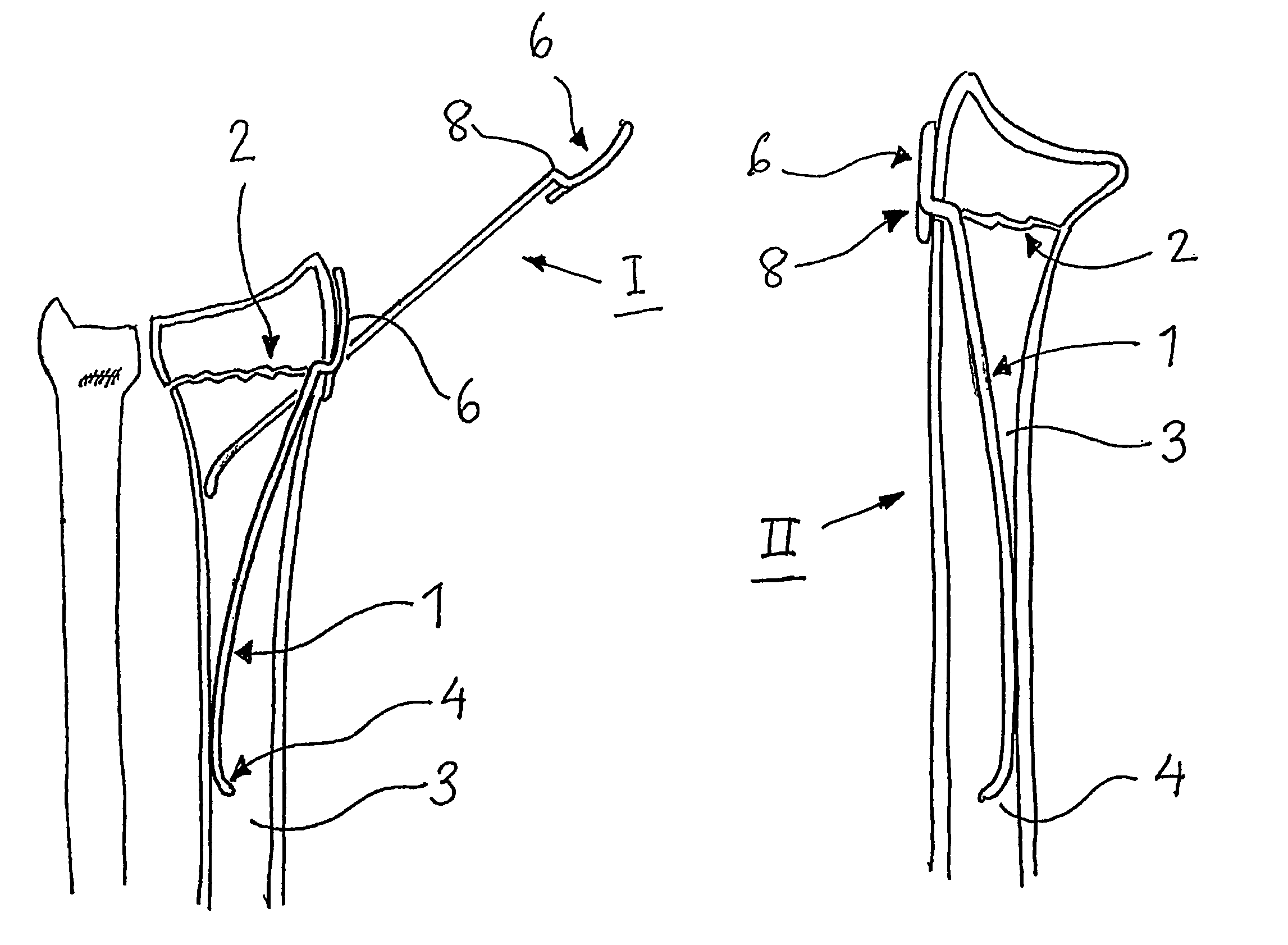
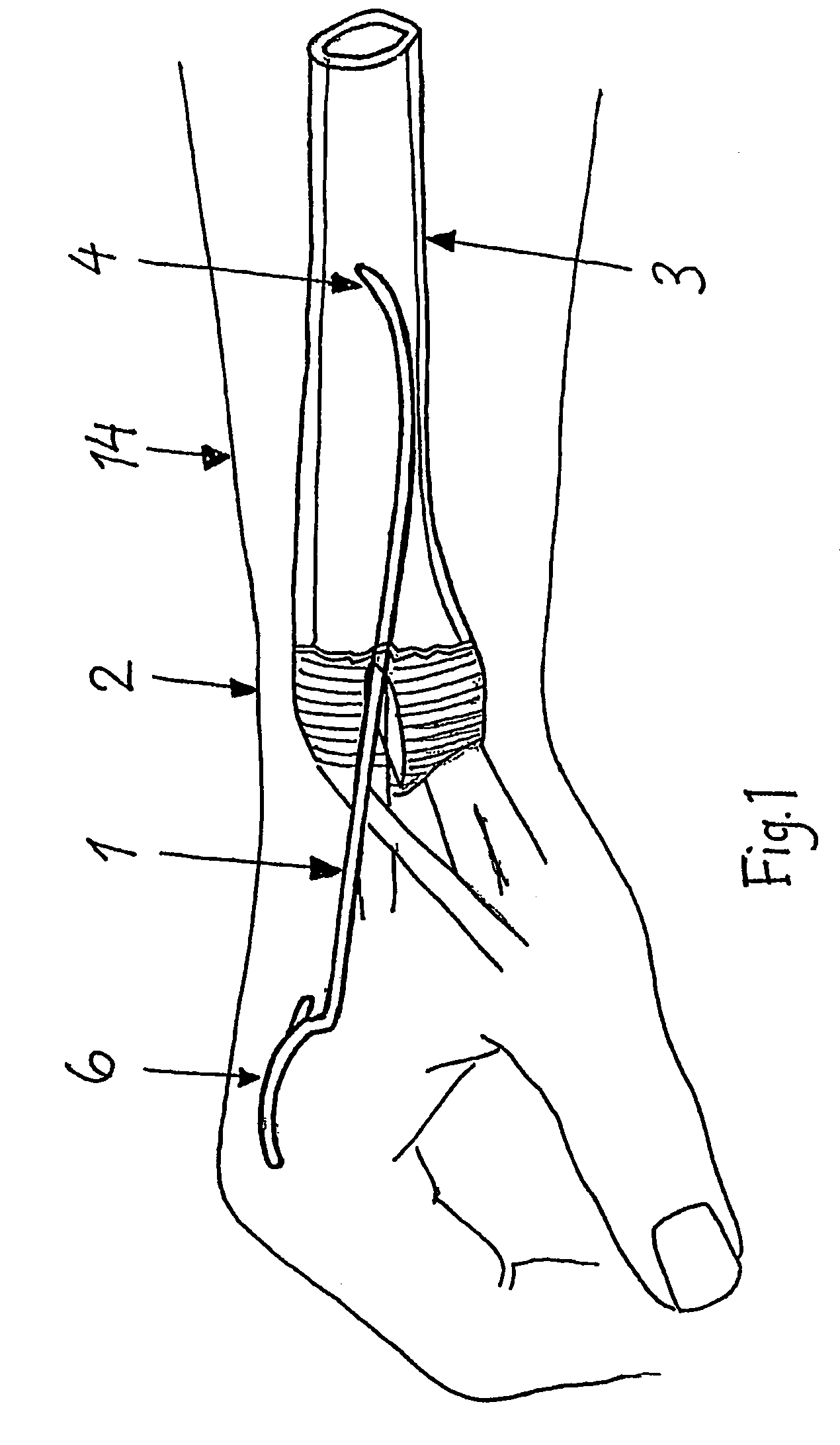
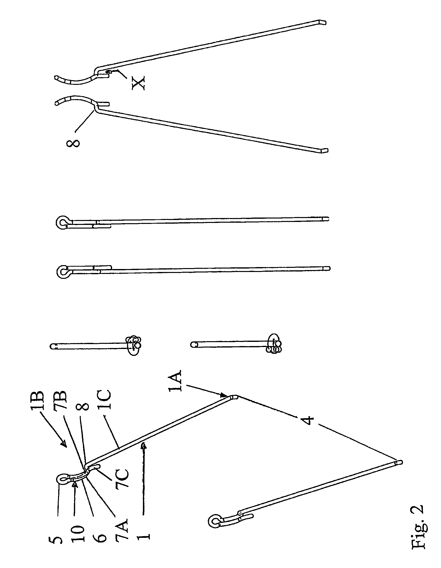
[0036]Referring to FIG. 1, a surgical fixation pin 1 in accordance with the present invention is included in a simple and effective system to be used as an aid when treating irregular distal radius and ulna fractures 2. The pin 1 is arranged to achieve maximum stability by using the smallest possible operation and implant. Pin 1 is further arranged to make it easy to insert through the fracture 2 and will be distinctive when inserted against the edge of the fracture in the proximal bone fragment in position in bone 3. A fixing device in the form of bone screw 9 (see FIG. 14) is ideal to be utilized together with a fixation pin of the type described herein to further achieve the stability of the fracture site. The insertion of the pin 1 is done through a small incision, as is shown in FIG. 1.

[0037]A pin 1 (FIGS. 1-4); 101 (FIGS. 5-10); 201 (FIG. 14) that is ideal for use with fracture 2 on bone 3 in arms 14 or other body parts, to achieve support and stability to the bone 3 when heal...


PUM


Abstract

A surgical fixation pin for use in fractures of bones in arms or other body parts to achieve support of the bone while the fracture heals. The pin is formed of a spring material and includes at opposite ends an angled, rounded front section and a double bent, extracortical section equipped with a fixation eye for receiving a fixation screw for securing the pin to a bone at a fracture site.

Description

BACKGROUND OF THE INVENTION[0001]1. Field of the Invention[0002]The present invention relates to a pin for use in fractured bones in arms or other parts of the body, to bring about support of the fractured bone while it is healing.[0003]2. Description of the Related Art[0004]It is generally known within the health care field that in the treatment of fractured bones means are used to allow reinforcement and support to the area surrounding a fracture in the bone in question.[0005]Fractures of the distal forearm (wrist fractures) are the most common of all fractures (annual incidence about 3,000 / 1,000,000 inhabitants in the industrialized world) and constitutes by it's abundance a major therapeutic problem. Simple fractures are treated with just a bandage while more complex fractures often require open reduction and plate fixation. For a large number of the intermediate complex fractures the choice of treatment is less obvious; while plate fixation may be a too extensive and expensive ...

Claims


Application Information

Patent Timeline
Patent Type & Authority Patents(United States)
IPC IPC(8): A61B17/04A61B17/84A61F2/08A61B17/86
CPCA61B17/6408A61B17/7208A61B17/7291A61B17/86A61B17/725A61B17/7233
Inventor ULLMAN, MICHAELEKHOLM, CARL
Owner SWEMAC INNOVATION
Learn More