Wind energy installation with an extended rotation speed range

a technology of wind energy installation and rotation speed range, which is applied in the direction of electric generator control, machine/engine, dynamo-electric converter control, etc., can solve the problem that the step-up ratio required per se is no longer feasible for very high-power generators, and narrows the usefulness and therefore the yield of wind energy installation

Active Publication Date: 2011-12-27
SIEMENS GAMESA RENEWABLE ENERGY SERVICE GMBH
View PDF9 Cites 12 Cited by
  • Summary
  • Abstract
  • Description
  • Claims
  • Application Information

AI Technical Summary

Benefits of technology

[0008]The mode selector allows the invention to act specifically on the converter regulation in order in this way to force the converter to operate in a specific operating mode, to be more precise from one or both inverters in the converter. During operation in the super-synchronous range, that is say at high load, it is possible for at least one of the inverters in the converter to be switched to under-excited operation. In consequence, the inverter produces an additional (inductive) reactive current, which reduces the voltage with respect to the rotor voltage. This makes it possible to prevent rotor voltage limit values being exceeded. Even at high power and thus at a high rotation speed, the wind energy installation can therefore be operated in the super-synchronous mode while nevertheless maintaining an adequate margin for the rotor voltage. The invention means that there is no longer any need to restrict the rotation speed in order to protect the generator or converter against excessively high rotor voltages.
[0011]The invention achieves a number of advantages. On the one hand, the usable rotation speed spectrum is extended while limiting the rotor voltage to specific maximum values. Since the rotation speed limits do not need to be reduced, the rotation speed margin is available to precisely the same extent as in installations of lower rating classes, so that the wind energy installation according to the invention also has correspondingly good gust resistance. In particular, the invention can therefore even be used to upgrade existing wind energy installations, with the generator being replaced by one with a higher rating; the design according to the invention means that there is no need for corresponding and costly replacement of the converter by one with a higher rating. The invention therefore makes it possible to operate a more powerful generator with a converter designed for a lower rating class, and nevertheless to maintain the usable rotation speed range.
[0012]A voltage sensor is preferably provided, which determines the voltage present on the stator of the generator and interacts with the mode selector such that the excitation of the generator is reduced as a function of the stator voltage. This allows a voltage drop (the difference between the rotor voltage and the stator voltage) across the generator to be set such that this results in a desired rotor voltage. The rotor voltage can therefore be protected against an undesirable rise, for example resulting from a network voltage or frequency which deviates from the standard value.
[0017]Furthermore, the converter regulation can be designed to measure and to monitor the rotor voltage. If the rotor voltage exceeds a predeterminable limit value, the converter regulation activates protective devices, such as a crowbar, in order to reduce the rotor voltage, and therefore protects the generator against damage caused by an excessive rotor voltage.

Problems solved by technology

One difficulty is that specific maximum and minimum rotation speeds must be complied with because of limiting parameters in the wind energy installation.
However, it has been found that the step-up ratio that is required per se is no longer feasible for very high-power generators.
In order nevertheless to allow the high power to be transmitted, it is either necessary to replace the converter for one with a higher voltage limit, which is expensive, or to restrict the rotation speed range of the wind energy installation, which narrows the usefulness and therefore the yield of the wind energy installation.
One particularly disturbing factor in restricting the rotation speed range, which is advantageous from cost viewpoints, is that the remaining rotation speed margin for wind strength fluctuations, in particular for gusts, is lost.
It is known that an undesirable rise in the rotor voltage when the network frequency is incorrect can be limited by switching to a different torque / rotation speed characteristic (US 2007 / 069522 A1).
This known approach has the disadvantage that the torque / rotation speed characteristic is shifted toward medium rotation speeds, thus inter alia reducing the intended maximum rotation speed.

Method used


Image

  • Wind energy installation with an extended rotation speed range
  • Wind energy installation with an extended rotation speed range
  • Wind energy installation with an extended rotation speed range

Examples


Embodiment Construction

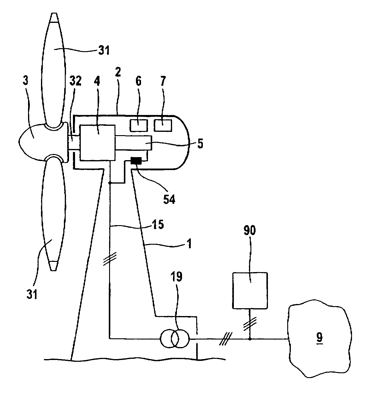
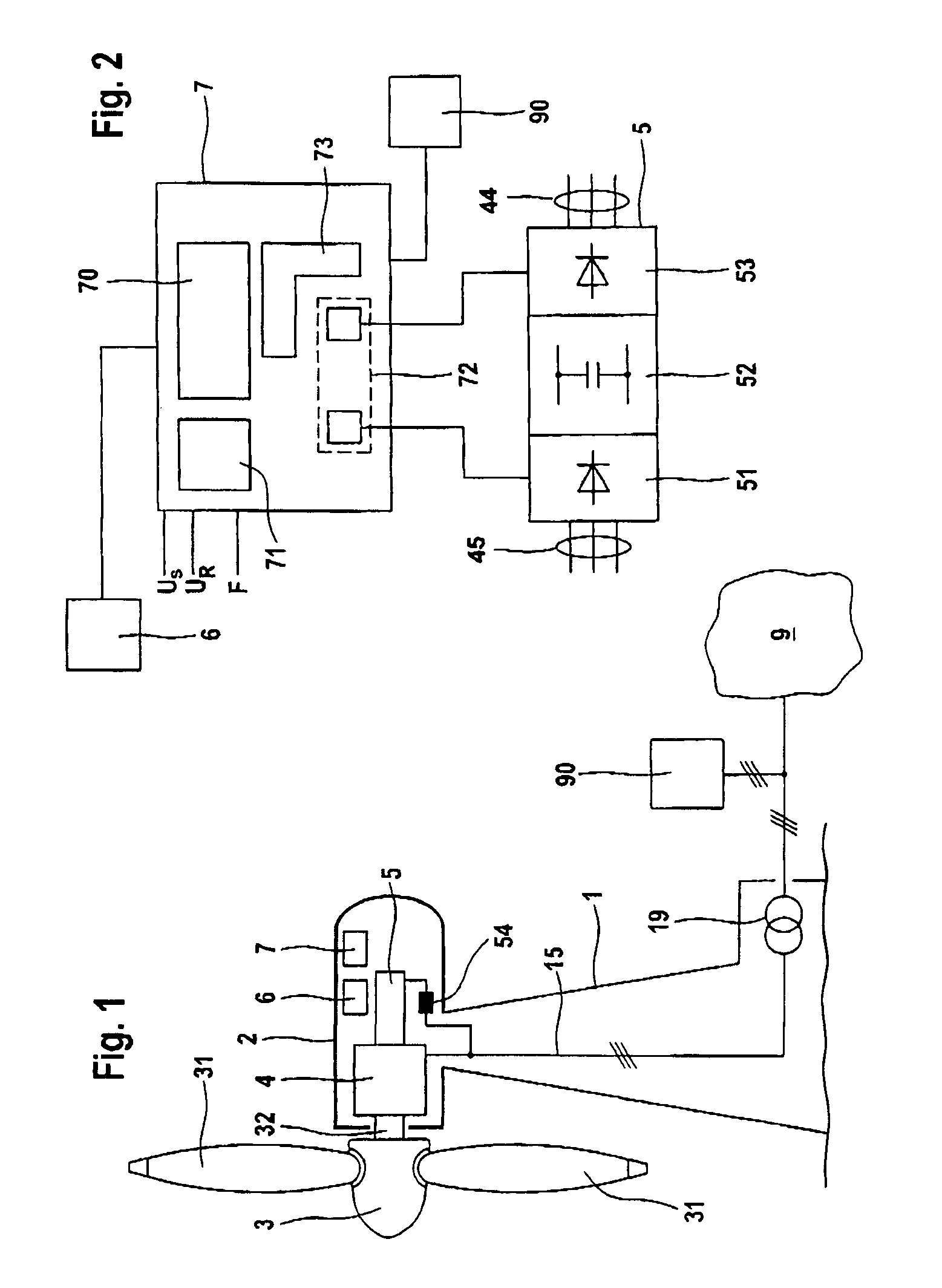
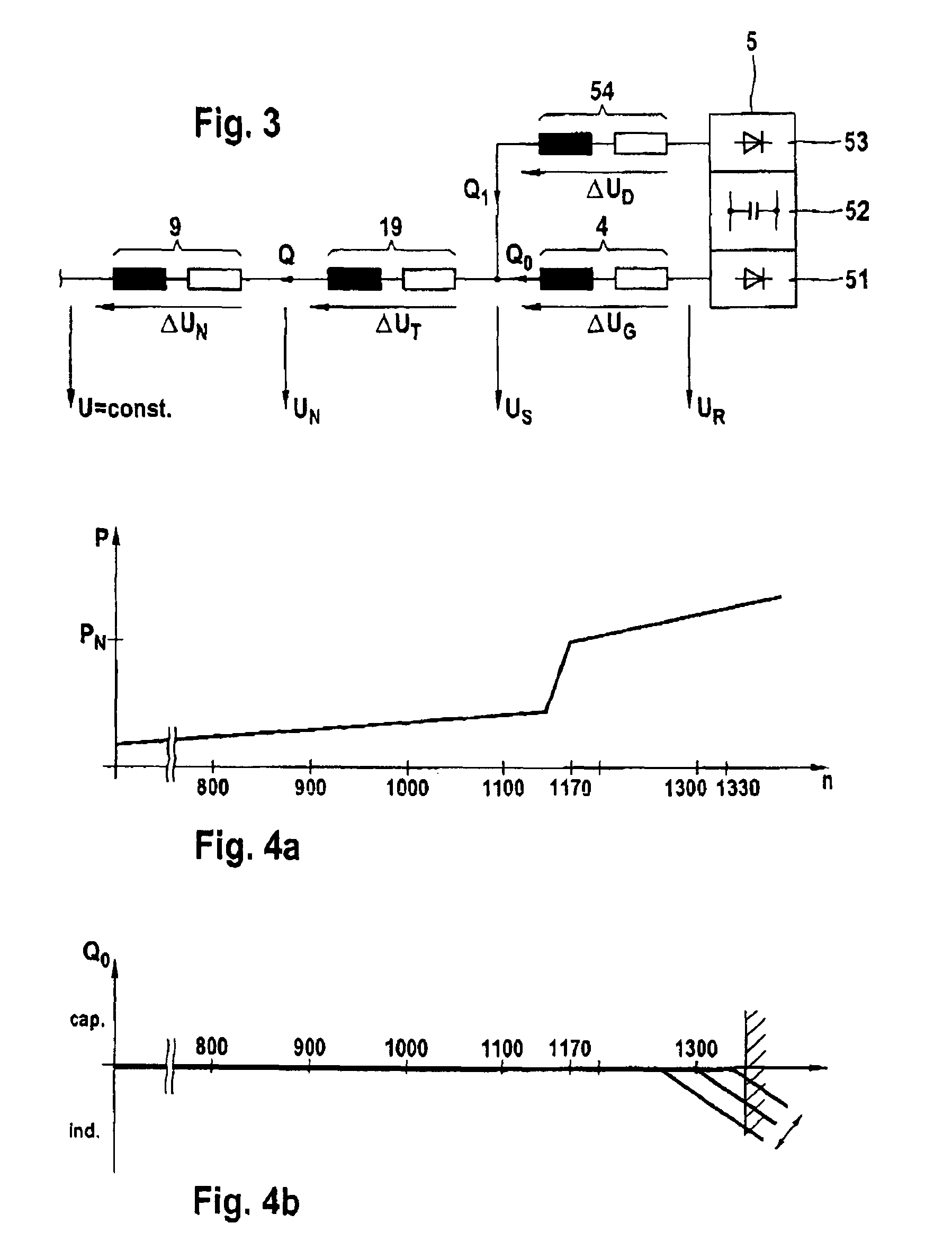
[0025]A wind energy installation designed according to one exemplary embodiment of the invention comprises a tower 1 at whose upper end a machine housing 2 is arranged such that it can rotate in the azimuth direction. A wind rotor 3 having a plurality (3 in the illustrated example) of variable pitch-angle rotor blades 31 is arranged on one end face of the machine housing 2. The wind rotor 3 drives a generator 4, which is arranged in the machine housing 2, via a shaft 32. The generator is a double-fed asynchronous generator with a stator and a rotor. A converter 5 and an operation controller 6 for the wind energy installation are also arranged in the machine housing, and the operation controller 6 is connected to converter regulation 7. The latter controls the converters and their inverters and directly selects the electrical parameters for the converter 5. The electrical power produced by the generator 4 in conjunction with the converter 5 is emitted to a network 9 via a line 15 and...


PUM


Abstract

A wind energy installation includes a wind rotor, a double-fed asynchronous generator driven by the wind rotor, a converter provided with a first part on the generator side connected to a rotor and a second part on the network side connected to a stator of the generator, and a control device providing converter regulation. A mode selector can be switched between a normal operating mode and a reduced voltage operating mode, in which the excitation of the generator is reduced compared to the normal operating mode. The under-excitation produces an additional reactive current, thus reducing the rotor voltage. The rotor voltage can be limited even when the load is high and the network frequency or voltage is incorrect. The usable rotation speed range of the wind energy installation can be extended to provide a more powerful generator with a higher rating, without changing the converter.

Description

CROSS REFERENCE TO RELATED APPLICATION[0001]This application claims the priority of German Patent Application No. 10 2007 032 179.3 filed Jul. 10, 2007, the contents of which are incorporated herein by reference.FIELD OF THE INVENTION[0002]The invention relates to a wind energy installation having a wind rotor, a double-fed asynchronous generator driven by the wind rotor, and a converter for feeding electrical power into a network, with a part on the machine side of the converter being connected to a rotor, and a part on the network side being connected to a stator of the double-fed asynchronous machine, and with a control device with converter regulation being provided, which regulates the converter on the basis of predetermined parameters in a normal operating mode.BACKGROUND OF THE INVENTION[0003]Modern wind energy installations, in particular those in the relatively high power classes in the Megawatt range, are designed to operate at variable rotation speeds. This means that the...

Claims


Application Information

Patent Timeline
Patent Type & Authority Patents(United States)
IPC IPC(8): H02P9/04
CPCH02J3/386Y02E10/763F03D7/0272F03D7/0276F05B2220/70646F05B2270/32H02J2300/28H02J3/381Y02E10/76Y02E10/72
Inventor LETAS, HEINZ-HERMANN
Owner SIEMENS GAMESA RENEWABLE ENERGY SERVICE GMBH
Why Eureka
Try Eureka