Method and system to detect zero current conditions in an electronic ballast by monitoring voltage across a buck inductor

a technology of zero current conditions and electronic ballasts, applied in the direction of electric variable regulation, process and machine control, instruments, etc., can solve the problems of energy inefficiency, lamp efficiency challenges, power loss, etc., and achieve the effect of reducing switching losses in electronic ballasts

Inactive Publication Date: 2011-12-27
UNIVERSAL LIGHTING TECHNOLOGIES
View PDF15 Cites 5 Cited by
  • Summary
  • Abstract
  • Description
  • Claims
  • Application Information

AI Technical Summary

Benefits of technology

[0007]To effectively reduce switching losses in electronic ballasts, the status of the transistors providing power signals to the lamp(s) must first be known. However, directly monitoring the power signals at the switching transistors is not a trivial endeavor. In some cases, such monitoring may impair the performance of the transistors and, more generally, the electronic ballast. However, monitoring the power signals associated with the buck inductor, a component in the power converter circuit driving the lamp(s), provides an accurate representation of the power signals associated with / loading the switching transistors, thereby indicating the switching transistors' status, without the deleterious effects mentioned above.

Problems solved by technology

However, using transistors to facilitate power delivery to the lamp can also present efficiency challenges.
Thus, if a power signal, comprised of both a current signal and a voltage signal, is present while the transistor is switching, a power loss will occur.
This leads to energy inefficiencies and is therefore undesirable.
Because of the transient and unpredictable nature of the power signal, minimizing switching losses is not an easy task.
Unfortunately, such a strategy has many deficiencies.
One such deficiency is that just because the voltage signal may be zero, or at a minimum, does not necessarily mandate that the current signal is also at a minimum.
If both current and voltage signals are not at their respective minimum values then the switching efficiency is not maximized.
Thus, strategies that rely solely on the state of the voltage level present at the transistor to reduce switching losses are not ideal.
Floating circuits are complex and, accordingly, costly and more prone to failure than non-floating circuits.

Method used


Image

  • Method and system to detect zero current conditions in an electronic ballast by monitoring voltage across a buck inductor
  • Method and system to detect zero current conditions in an electronic ballast by monitoring voltage across a buck inductor
  • Method and system to detect zero current conditions in an electronic ballast by monitoring voltage across a buck inductor

Examples


Embodiment Construction

[0021]The present invention relates generally to electronic ballasts for gas discharge lamps. More specifically, this invention relates to an electronic ballast with a zero-current detection circuit.

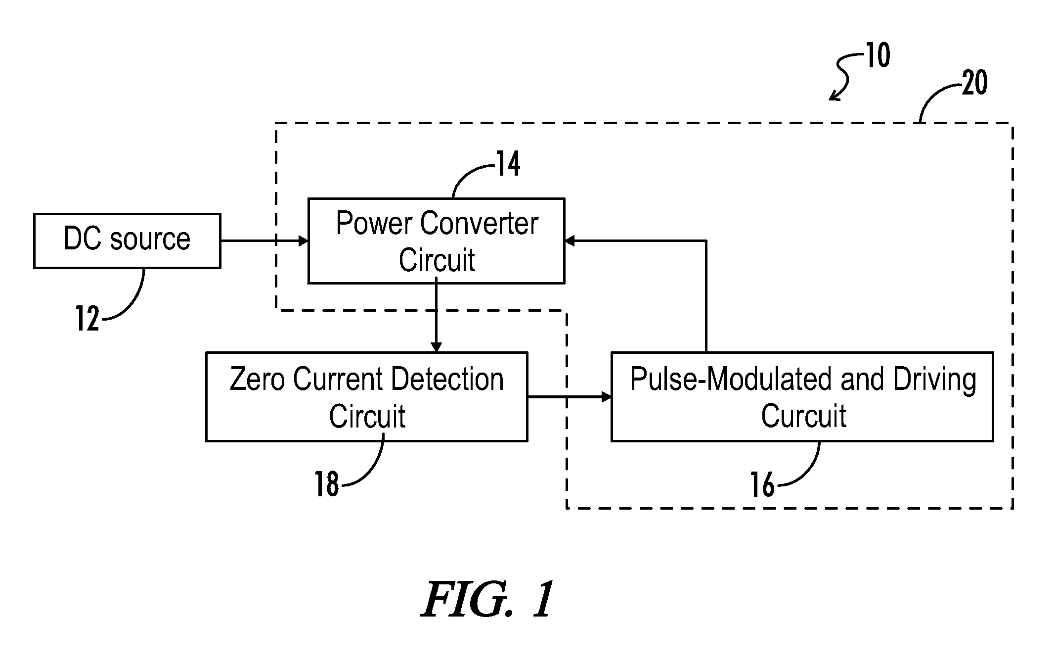
[0022]FIG. 1 is a block diagram of a portion of an electronic ballast 10. The block diagram illustrates a DC source 12 supplying power to the ballast 10. The DC source 12 may be a generator providing a DC signal. The DC source 12 may also describe the output of a rectifier circuit that accepts AC signals from an AC source and converts them into substantially constant DC signals. Further, the DC source 12 may describe the output of a power factor correcting circuit (or combination power factor correcting and boost circuit) that accepts a DC signal input, usually from a rectifier circuit, and generates a DC signal at a desired level and ensures that the power factor of the AC source does not deviate from a predetermined range.

[0023]The DC source 12 is coupled to a power converter circuit 1...


PUM


Abstract

The invention discloses a method and system to detect zero current conditions in a buck inductor by monitoring the voltage across the buck inductor. Once zero current and voltage conditions are present, an inverter circuit changes the operational state, i.e. conducting or non-conducting, of the switching transistors driving the lamps to reduce power loss associated with changing the operational state of switching transistors when under a load.

Description

BACKGROUND OF THE INVENTION[0001]The present invention relates generally to electronic ballasts for gas discharge lamps. More specifically, this invention pertains to electronic ballasts having circuitry to provide for zero-current switching of the ballast switching transistors.[0002]The operation of a gas discharge lamp requires, among others, a mechanism to control the current delivered to the lamp. Initially, this role was satisfied by magnetic ballasts. However, with the proliferation of integrated circuits, the focus has turned to electronic ballasts to manage the operation of the lamp. The migration from magnetic ballasts to electronic ballasts is due, in significant part, to the increased operational efficiency afforded by electronic ballasts, relative to magnetic ballasts.[0003]The increased efficiency of electronic ballasts is attributable to several factors, one key factor being the use of switching transistors to alter the frequency of the power signals received from the ...

Claims


Application Information

Patent Timeline
Patent Type & Authority Patents(United States)
IPC IPC(8): H05B37/02
CPCH05B41/28H02M7/53803
Inventor SHIWEI, YUQIN, GAOSUI, GUO
Owner UNIVERSAL LIGHTING TECHNOLOGIES
Why Eureka
Try Eureka