Method and apparatus for dynamic modulation

a dynamic modulation and apparatus technology, applied in the field of analog and digital circuits for signal modulation, can solve the problems of increasing the cost and size of the power supply, power consumption, and requiring costly suppression measures or extensive shielding, and achieve the effect of passing the regulatory requirements

Inactive Publication Date: 2011-12-27
HUDA MUZAHID BIN +1
View PDF12 Cites 55 Cited by
  • Summary
  • Abstract
  • Description
  • Claims
  • Application Information

AI Technical Summary

Problems solved by technology

Switch Mode Power Supplies (SMPS) tend to generate EMI due to rapid switching of current and voltage.
In order to comply with such regulatory limits on EMI emissions, costly suppression measures or extensive shielding may be required.
An EMI filter causes power consumption and increases the cost and size of the power supply.
Frequency modulation alone is not necessarily able to reduce EMI enough to meet the regulation requirements, such as Quasi-Peak measurement.
And, although spread spectrum modulation with fixed modulation depth may smear the peak EMI energy out into additional sidebands, it is not adequate to address the difficulties associated with reducing the spectral amplitudes of EMI in lower harmonics, such as the second and third harmonics.

Method used


Image

  • Method and apparatus for dynamic modulation
  • Method and apparatus for dynamic modulation
  • Method and apparatus for dynamic modulation

Examples


first embodiment

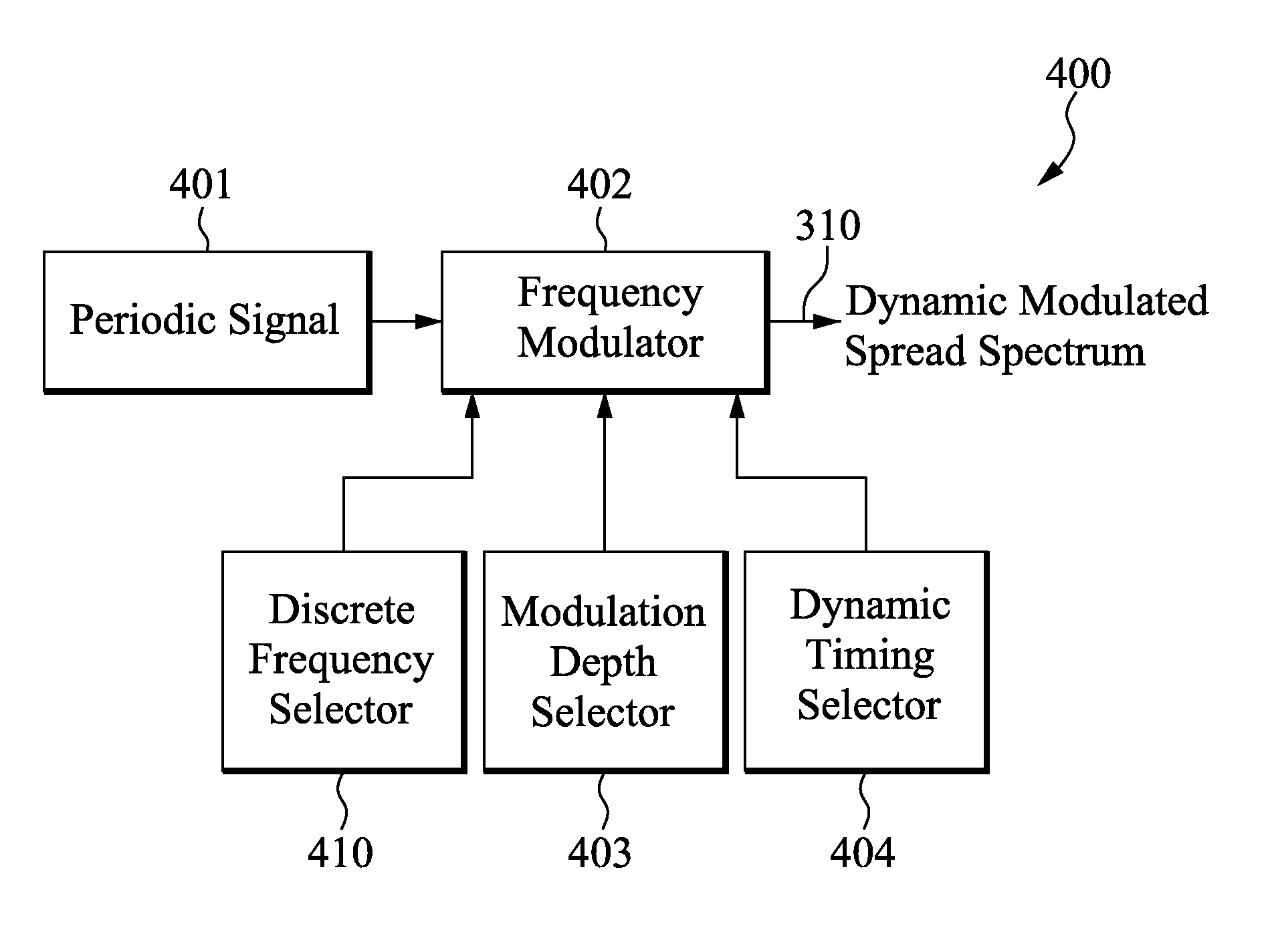
Now refer to FIG. 5A which illustrates the timing of a dynamic modulator with modulation depth control only, dynamic modulator, in accordance with the present invention. The switching signal is frequency modulated at modulation depths δ1, δ2, δ3, . . . , δn over time which are set by modulator depth selector 403. The time duration (dwell time), set by dynamic timing selector 404, over which the modulated frequency remains at each value of δ determines the resulting time averaged amplitudes of the carrier frequency, its harmonics and their sidebands. 501, 502, 503, 504 and 505 represent the spread spectrum modulation depth values of δ1, δ2, δ3, . . . , δn and δ1 that are impressed on the switching frequency. The parameters td 506 and tr 507 are the dwell time and repetition period respectively. Parameter td 506 represents the time duration over which modulation depth δ1 is impressed on the switching frequency to effect spread spectrum modulation. Also, tdn 508 represents a general du...

second embodiment

Turning to FIG. 5B which illustrates the timing of a dynamic modulator with discrete frequency hopping control, dynamic modulator, in accordance with the present invention. It shows the concept of discrete frequency variation (hopping) for conducted and radiated emissions compliance when standard Quasi Peak (QP) detection methodologies for radiated and / or conducted EMI measurement are used. The switching frequency is shifted over a range of values f1, f2, f3, . . . , fn as represented by 521, 522, 523, 524 and 525. 506 represents the dwell time (td) at each value of the frequency and 507 represents the repetition period (tr) at each of the frequencies selected for hopping. The dwell time 506 may be set to be equal for all frequencies f1-fn, and f1 (i.e. 521-525), or it may be set to be varied for each frequency value 521-525. This idea is shown as the parameter tdn 508, where tdn is the dwell time at the nth frequency fn. The dwell time tdn 508 may or may not be equal to td 506. The...

third embodiment

As mentioned earlier, the discrete frequency hopping of dynamic modulator can operate independently or with modulation depth changes (or control). FIG. 5C illustrates the timing of this combined control, dynamic modulation. In FIG. 5C, the vertical axis is frequency and horizontal axis is time. The values and scale of frequency and time are for illustration only. During the first time interval td 506 (or dwell time), frequency f1 is set to 120 kHz and modulation depth δ1 501 is also applied. In the next time interval, frequency is shifted to 160 kHz while modulation depth δ2 502 is used. At the nth time interval tdn 508, the frequency fn is set to 80 kHz with modulation depth δn 504. Also, tdn 508 represents a general duration of the dwell time, and td 506 may or may not be equal to tdn 508. Note that the values of modulation depths (δ1 to δn) used in discrete frequency hopping control may be the same or different, periodically, non-periodically or randomly. They are used to further...


PUM


Abstract

Circuits and methods of dynamic modulation are disclosed. A dynamic modulator is used to reduce measurable conducted and / or radiated electromagnetic interference (EMI). The dynamic modulator is configured to generate either a set of optimal frequency modulation depths or discrete frequencies or both, and dynamically selects them to use over a series of programmable time durations (dwell time). Together with the utilization of Peak, Average or Quasi-Peak (QP) method of measurement, the dynamic modulator can reduce the spectral amplitude of EMI components, in particular the lower harmonics, to effectively pass regulatory requirements. In alternative embodiments, the dynamic modulator is used in a closed loop system to continuously adjust the frequency and the duty cycle of a PWM signal to reduce conducted and / or radiated EMI.

Description

BACKGROUND1. Field of InventionThe present invention relates generally to the fields of both analog and digital circuits for signal modulation. More specifically, the present invention relates to a method and an apparatus for dynamically modulating periodic signal from PWM to reduce measurable radiated and / or conducted electromagnetic interference (EMI).2. Description of the Related ArtSwitch Mode Power Supplies (SMPS) tend to generate EMI due to rapid switching of current and voltage. The spectral components of the EMI emissions typically have peak amplitudes at harmonics of the fundamental frequency of a clock. Accordingly, many regulatory agencies, such as the FCC in the United States, have established testing procedures and maximum allowable emissions for such products. For example, the Commission Electrotechnique Internationale (Comite International Special Des Perturbations Radioelectriques (C.I.S.P.R.)) has guidelines establishing measurement equipment and techniques for dete...

Claims


Application Information

Patent Timeline
Patent Type & Authority Patents(United States)
IPC IPC(8): H03C3/06H03K7/06
CPCH03K3/84H03K7/08
Inventor HUDA, MUZAHID BINYU, HO-YUAN
Owner HUDA MUZAHID BIN
Why Eureka
Try Eureka