
Armored glass composition with perimeter reinforcement

a technology of armored glass and composition, applied in the direction of protective equipment, layered products, weapons, etc., can solve the problems of generating internal stresses at the interface between the painted area and the glass, not providing a complete solution to the ballistic weakness problem, and not offering total protection of the protected space, so as to achieve effective ballistic protection and effective ballistic solution

Active Publication Date: 2012-01-03
AGP AMERICA
View PDF12 Cites 14 Cited by
  • Summary
  • Abstract
  • Description
  • Claims
  • Application Information

AI Technical Summary

Benefits of technology

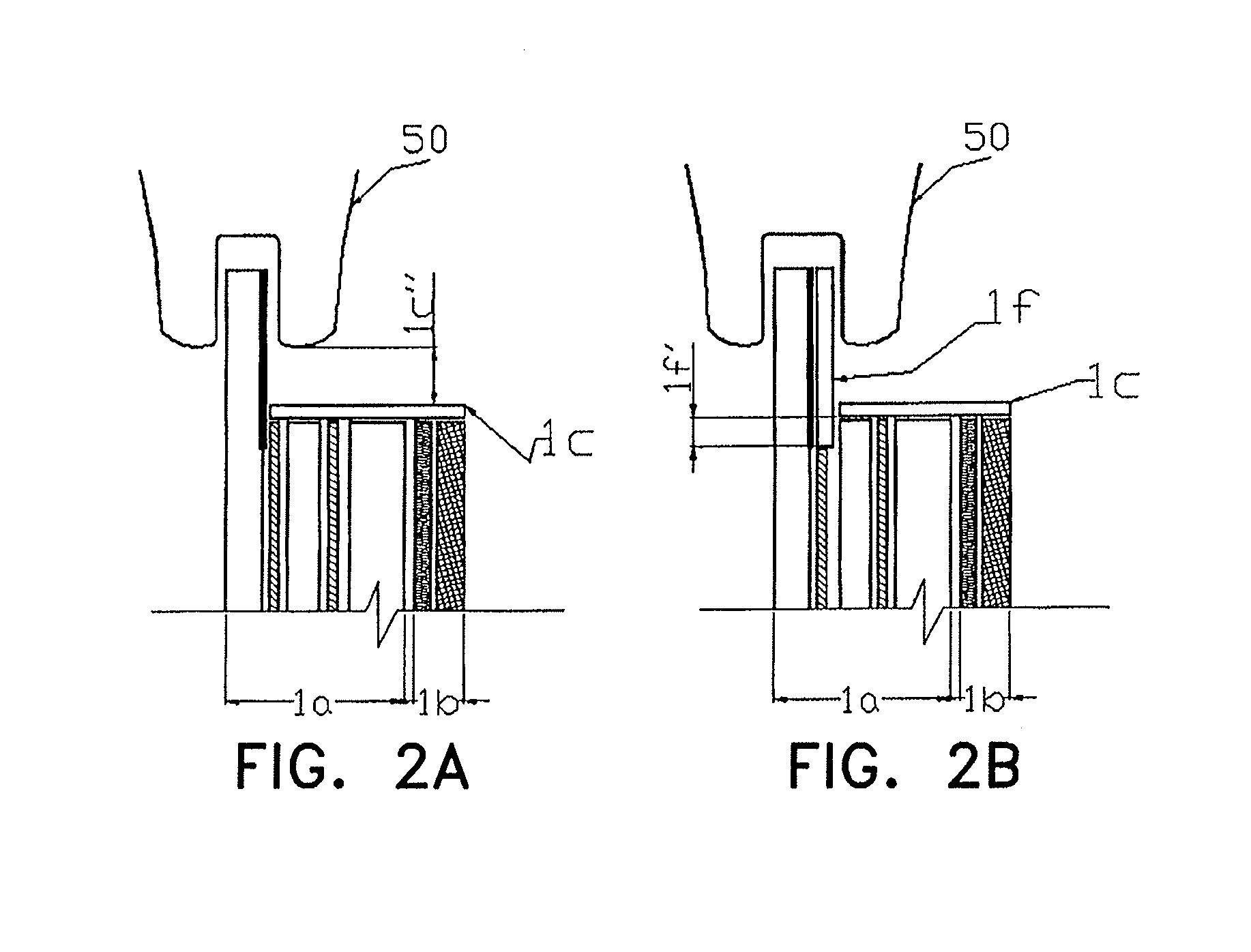
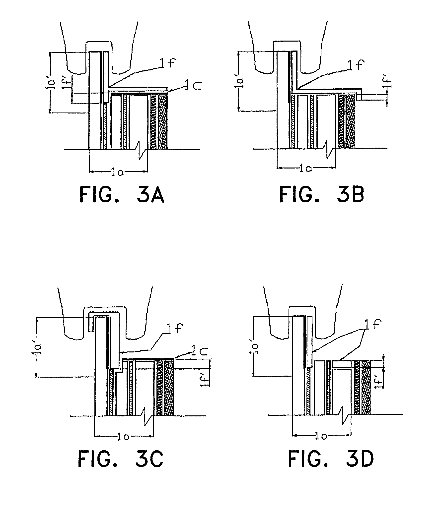
"The present invention provides a way to protect armored glass from attacks. This is done by adding special materials to the edges of the glass, which allows for controlled deformation and energy absorption. This results in effective ballistic protection, stopping projectiles and splinters from entering the protected space. This solution does not require adding extra protection elements outside of the armored glass."

Problems solved by technology

), that differences in glass and paint heat expansion coefficients induce differences in glass and paint dilation, leading to the generation of internal stresses within the interface of the painted area and the glass.
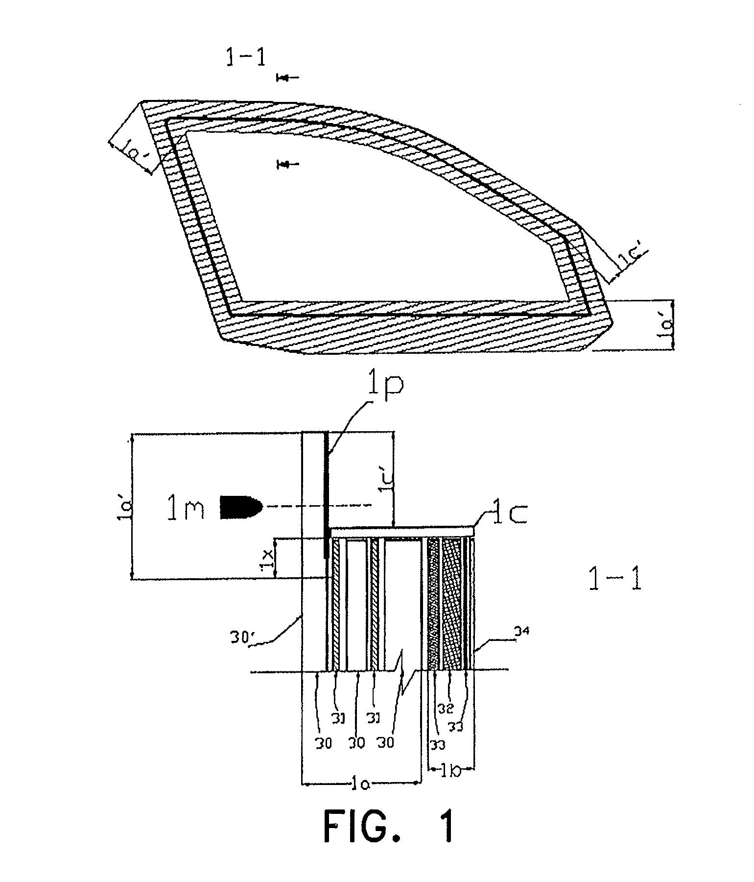
The solutions posed by the prior art that include some reinforcement element incorporated in the armored glass composition, do not provide a complete solution to the ballistic weakness problem of zone 1a′.
The options provided incorporate highly rigid designs on the armored glass edge which upon strict ballistic testing, do not offer total protection of the protected space.
Before ballistic testing such as the one described above, the prior art does not efficiently provide an armored glass composition that provides complete ballistic retention protection, either of impacts or splinters (or glass or projectile residue) over area 1a.
In other words, making reference to FIG. 4, prior art does not assure that a BRG composition that complies with a set ballistic resistance in its central area in accordance to some recognized ballistic standard, will comply with the same ballistic protection over area 1a′ when this area is hit with the same ammunition as the central area.
This failure also produces rupture of the BRG's third set 1c.

Method used


Image

  • Armored glass composition with perimeter reinforcement
  • Armored glass composition with perimeter reinforcement
  • Armored glass composition with perimeter reinforcement

Examples


Embodiment Construction

[0042]Within an armored glass composition, each one of the differentiated sets in FIG. 1 has a specific function from a ballistic perspective. The first set 1a, comprised of a series of glass layers bonded together by the use of polymeric adhesives, works as a set which absorbs the greatest amount of projectile energy. This is the result of the increased hardness of the different glass layers 30 and the elastic capacities of the layered set which form these glass layers together with the polymer adhesives 31 which unite them. The second set 1b, primarily comprised by an impact energy absorber (IEA) element 32 which in most cases is a polycarbonate layer, and by the adhesives that are used to bond this IEA to the first set 1a, has the function of a highly elastic body which absorbs projectile residual energy which did not dissipate in the first set 1a. Hence, deformation (strain) of the second set 1b before projectile impacts may be several times greater compared to the first set 1a....


PUM

PropertyMeasurementUnit
heightaaaaaaaaaa
penetration distanceaaaaaaaaaa
distanceaaaaaaaaaa

Abstract

The invention relates to a special array of materials located on the periphery of a glass armored composition (BRG), with the purpose of having a controlled deformation zone being able to absorb residual energy of impacts made on the edge of the armored piece, therefore providing an effective retention of the projectile and of the glass fragments generated by the impact. The invention provides superior ballistic protection for BRGs destined for automobile applications, for fixed and mobile pieces.

Description

[0001]This is a national stage of PCT / IB2005 / 003094 filed 28 Sep. 2005 and published in English.FIELD OF THE INVENTION[0002]The invention is related to bullet-proof glass armored compositions (BRG), for automobile and architectural applications. These compositions conventionally consist of a set of glass layers joined together by polymer layers (in most cases, Polyvinyl Butyral (PVB) and Polyurethane (PU)) and a layer of Polycarbonate. Among currently used transparent armored compositions for glass automobile applications, three primary parts can be distinguished, which will be described making reference to FIG. 1. First, in reference to cross section 1-1 and starting from the outside in (“exterior” or “outside” meaning space from which a bullet is normally shot from, and “external” as a layer face of a BRG set located furthest from the set's center; likewise, “interior” refers to the closed space protected by the BRG, and “internal” as a layer face of a BRG set located nearest the ...

Claims


Application Information

Patent Timeline
Patent Type & Authority Patents(United States)
IPC IPC(8): B32B7/02
CPCB32B17/10045B32B17/10293B32B17/10366B32B17/10761F41H5/0407F41H5/263B32B17/1077Y10T428/24942B32B2369/00Y10T428/24967
Inventor MANNHEIM ASTETE, ARTUROBOCANEGRA PARRA, VLADIMIR
Owner AGP AMERICA
Learn More