Fluid level control toggle valve device and method

a technology of flue level control and toggle valve, which is applied in the direction of valve operating means/releasing devices, mechanical equipment, transportation and packaging, etc., can solve the problems of clogging of the basket, the basket being much smaller than the skimmer basket, and the damage of the pump motor, etc., to achieve automatic addition of water, low installation requirements, and low cost

Inactive Publication Date: 2012-01-10
BUCHTEL MICHAEL E
View PDF32 Cites 2 Cited by
  • Summary
  • Abstract
  • Description
  • Claims
  • Application Information

AI Technical Summary

Benefits of technology

[0007]It is an object of the invention to provide a device and method for automatically adding water to a swimming pool and the like when the water level has dropped below a desire level. It is yet another object to provide such a device with an anti-siphoning method for preventing pool water from siphoning into the water supply. It is further an object of the invention to provide a device without the need for fastening to pool structures while providing the device having low cost, low installation requirement and low maintenance. Another object is to provide a portable device that can be used with a standard garden hose and hose spigot for a water source. It is an object to limit turbulent water flow noise in the device at its operating position within the pool. Further, it is an object of the invention to provide a visible tell-tail for indicating an operating status in the device in its operating mode within the pool. Another object is to provide a adjustable water level gage for insuring a desired water level is being maintained by the device. It is yet another object of the invention to provide a device that is easily installed and adjusted to a desired water level at pool side.

Problems solved by technology

If the water level drops below the skimmer and causes the pump to run dry, serious pump motor damage can occur.
When sufficient air is drawn into the skimmer circulation system, the pump looses its prime, the impeller starts cavitation-pitting, or the pump motor over heats causing the pump motor burn-out and destruction of the pump seals.
The pump basket being much smaller than the skimmer basket will eventually clog.
Thus, relying on the drain to do the work of the skimmer means more debris on the pool bottom and more frequent pump basket clogs.
Cleaning the pool bottom and the pump basket are difficult tasks.
Overfilling the pool can be more costly than under filling.
If the water seeps under the pool deck and saturates the sub-soil, unsightly cracks or uneven deck tilting can occur.
Some are meant for industrial use indoors and do not operate well in swimming pools due to wind and wave action.
Those meant for use in swimming pools are expensive and must be installed while the pool is being built.
Of those intended for use over the top of the pool deck most are expensive, bulky and marginally portable requiring that ballast water be drained out or that heavy sand bag ballasts be moved.
Furthermore, few devices indicate when the desired water is achieved or indicate when the device is operating and few shut off automatically when removed from the pool to prevent swimmers from tripping over the supply hose.
In addition, background art gives little consideration to the electrolytic effect of supply water moving past the valve outlet aperture and causing electrolysis resulting in pool equipment metal erosion and plaster discoloration.
Consequently, bending the nozzle, washer and rod requires substantial torquing moments and downward ballast forces to unseat the valve against a water supply pressure.
As the device approaches its shut-off point, its make-up water slowly trickles down the cord and through the eyelet in the cap thus letting the water displace the air in the float and causing the float to become even heavier.
Consequently, the device adds more water to the pool, changes the water level, and overfills the pool, especially when rainwater or swimmer splashes enter the eyelet in the cap on the jar.
Further, the device is sensitive to rapid up and down and rocking motions due to pool water surface waves being directly coupled to water in the jar causing possible damage to plumbing.
Also, the materials used for such structures are generally buoyant and thus require substantial cantilevers or tie-down fasteners to hold the devices near a pool deck.
Further, placement next to the deck inevitably interferes with the wall climbing features of automatic pool cleaners.

Method used


Image

  • Fluid level control toggle valve device and method
  • Fluid level control toggle valve device and method
  • Fluid level control toggle valve device and method

Examples


Embodiment Construction

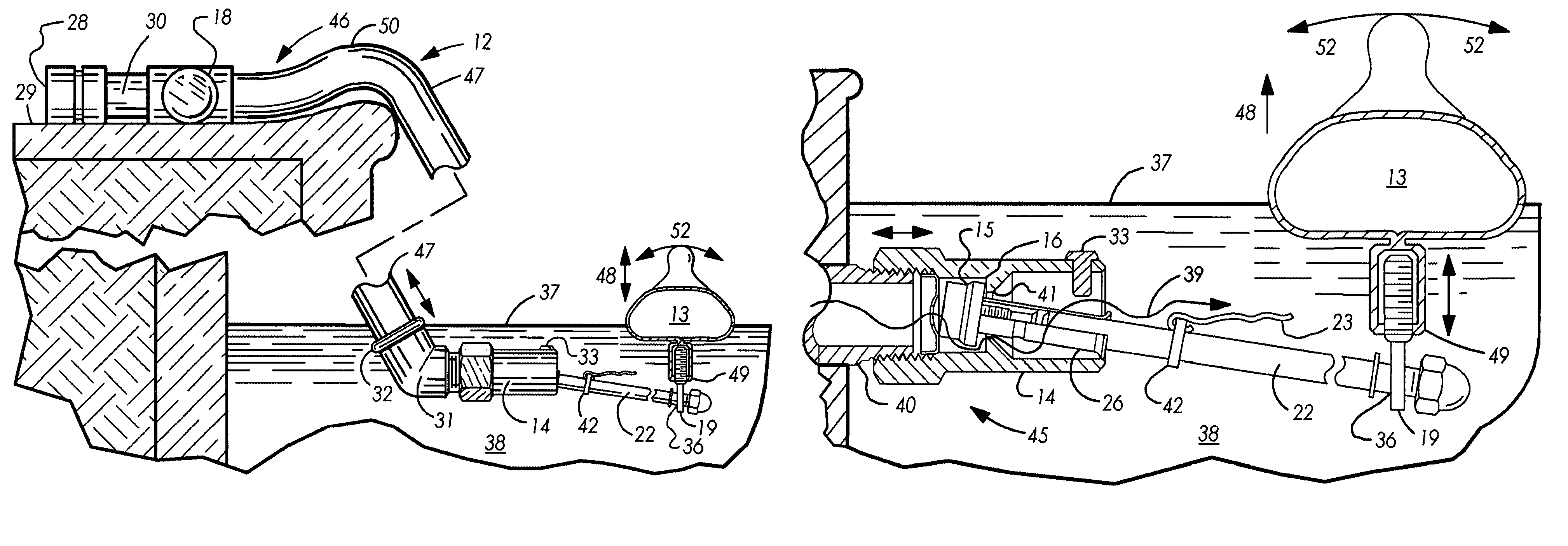
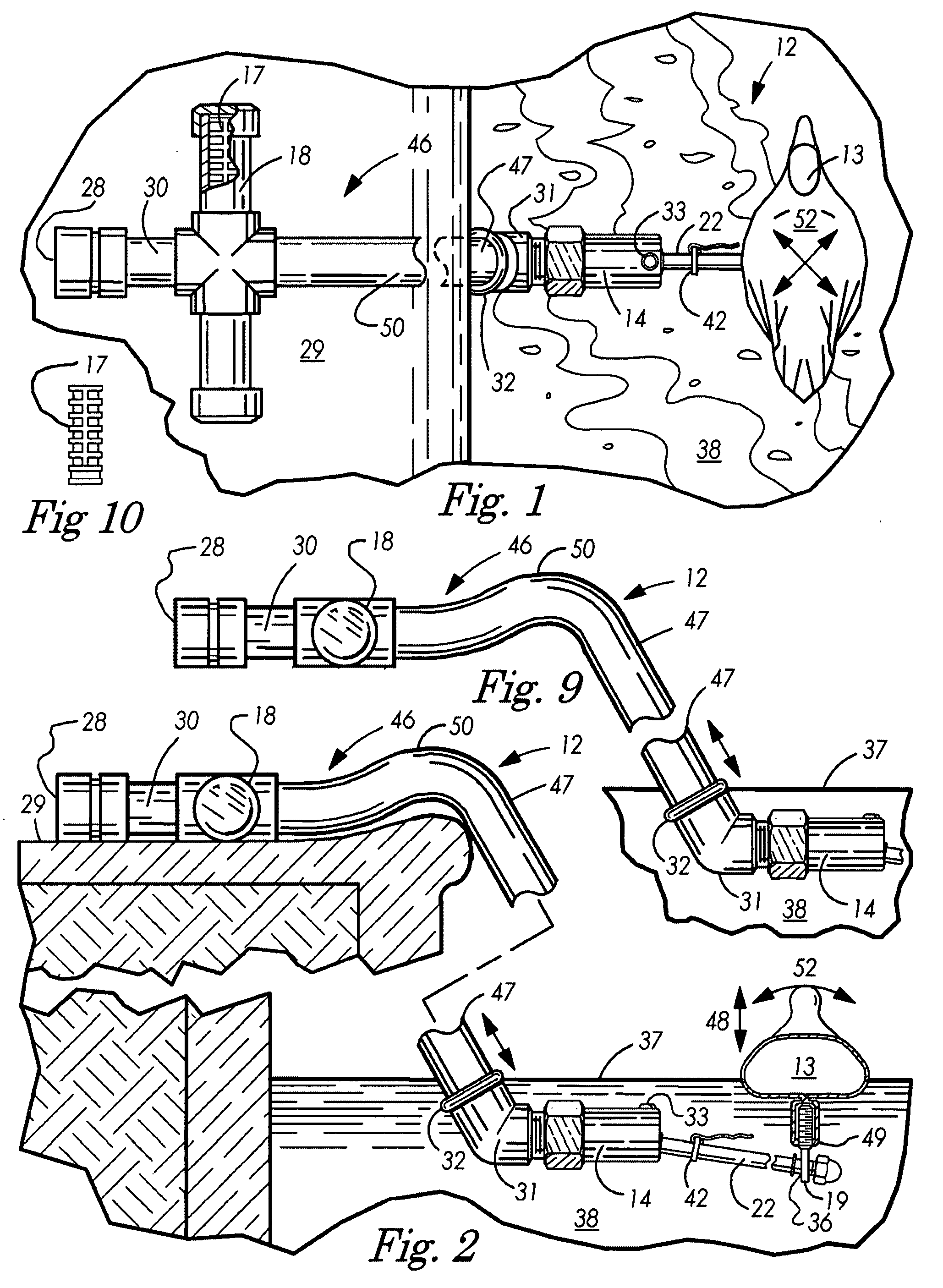
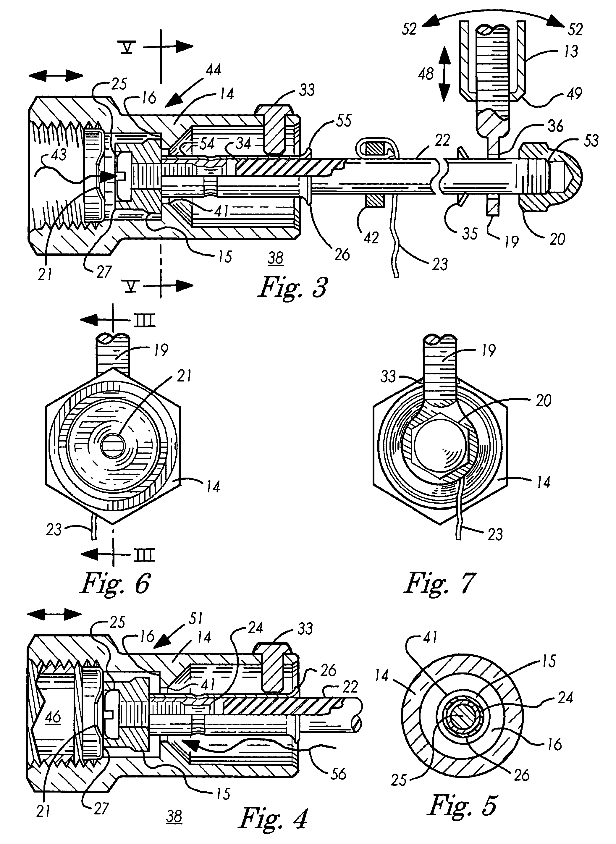
[0022]The preferred embodiment of the present invention is a water level control device 12 comprising a valve housing 14, a detachable float rod 22, a rod holder 26, a float 13, and a tell-tail assembly 23, as illustrated with reference to FIG. 2. The valve housing 14, serves as a support for a hose attachment connection pipe 46, a ballast 17, and an outrigger assembly 18, again as illustrated with reference to FIG. 1, FIG. 2 and to FIG. 9. The valve housing assembly 14 serves as a support for a hose attachment connection pipe 46, a ballast 17 and an outrigger assembly 18 again as illustrated with reference to FIG. 1. and FIG. 2. The valve housing assembly 14 serves to house an apertured flow reducer 21, a valve washer 15, a rod holder elevation stop 33 and a rod holder assembly 26 as illustrated with reference to FIG. 3. The float rod assembly first end 34 inserts into the rod holder assembly second end 55 for operation with the float assembly 13 and the rod holder assembly 26. The...


PUM


Abstract

A water level control device has connected tubular housings, one serving as a support for a hose connection and the other serving to support a valve housing assembly for operation of a toggle valve within the valve housing. An airtight float serves to raise the one extreme of a float rod when buoyed by sufficient water level admitted through apertures in the valve housing. The other extreme of the float rod is attached to a rod holder to hold the float rod. The rod holder passes through an outlet apertured valve seat wherein a valve washer attached to the rod holder within the toggle valve cavity is urged against the outlet valve seat by water pressure from a water hose.

Description

BACKGROUND OF INVENTION[0001]1. Field of Invention[0002]The present invention relates generally to fluid level control, and more particularly to maintaining a desired water level in a swimming pool.[0003]2. Background Art[0004]Swimming pools lose water everyday by evaporation from the sun regardless of the size of the pool. Pools can lose as much as one-quarter inch of water into the atmosphere on a typical day. Water loss in the pool as little a one inch typically drops the water level in the pool below that necessary for the proper use of the skimmer and circulating pump. If the water level drops below the skimmer and causes the pump to run dry, serious pump motor damage can occur. When sufficient air is drawn into the skimmer circulation system, the pump looses its prime, the impeller starts cavitation-pitting, or the pump motor over heats causing the pump motor burn-out and destruction of the pump seals. It is therefore important to be able to maintain the water level above the ...

Claims


Application Information

Patent Timeline
Patent Type & Authority Patents(United States)
IPC IPC(8): F16K31/18
CPCF16K31/26Y10T137/7439Y10T137/7485
Inventor BUCHTEL, MICHAEL E.
Owner BUCHTEL MICHAEL E
Why Eureka
Try Eureka