Motor vehicle and control method of motor vehicle

a technology of motor vehicles and control methods, which is applied in the direction of electric propulsion mounting, machines/engines, transportation and packaging, etc., can solve the problems of unfavorable deterioration of resin components, and achieve the effect of adequate cooling performan

Active Publication Date: 2012-01-10
TOYOTA JIDOSHA KK
View PDF18 Cites 54 Cited by
  • Summary
  • Abstract
  • Description
  • Claims
  • Application Information

AI Technical Summary

Benefits of technology

[0005]In a conventional structure of the motor vehicle, an engine is located on the rear side of the radiator in the engine room. In a state where the cooling water has a low temperature and circulation of the cooling water to the radiator stops, a temperature rise of the engine may undesirably facilitate deterioration of resin components, such as cable, clips, and casings, located in the periphery of the engine. It is thus desired to cool down the engine, separately from the performance of cooling down the engine by the cooling water. It is also desired to cool down the cooling water in the radiator.

Problems solved by technology

In a state where the cooling water has a low temperature and circulation of the cooling water to the radiator stops, a temperature rise of the engine may undesirably facilitate deterioration of resin components, such as cable, clips, and casings, located in the periphery of the engine.

Method used


Image

  • Motor vehicle and control method of motor vehicle
  • Motor vehicle and control method of motor vehicle
  • Motor vehicle and control method of motor vehicle

Examples


Embodiment Construction

[0029]Some modes of carrying out the invention are described below as preferred embodiments with reference to the accompanied drawings.

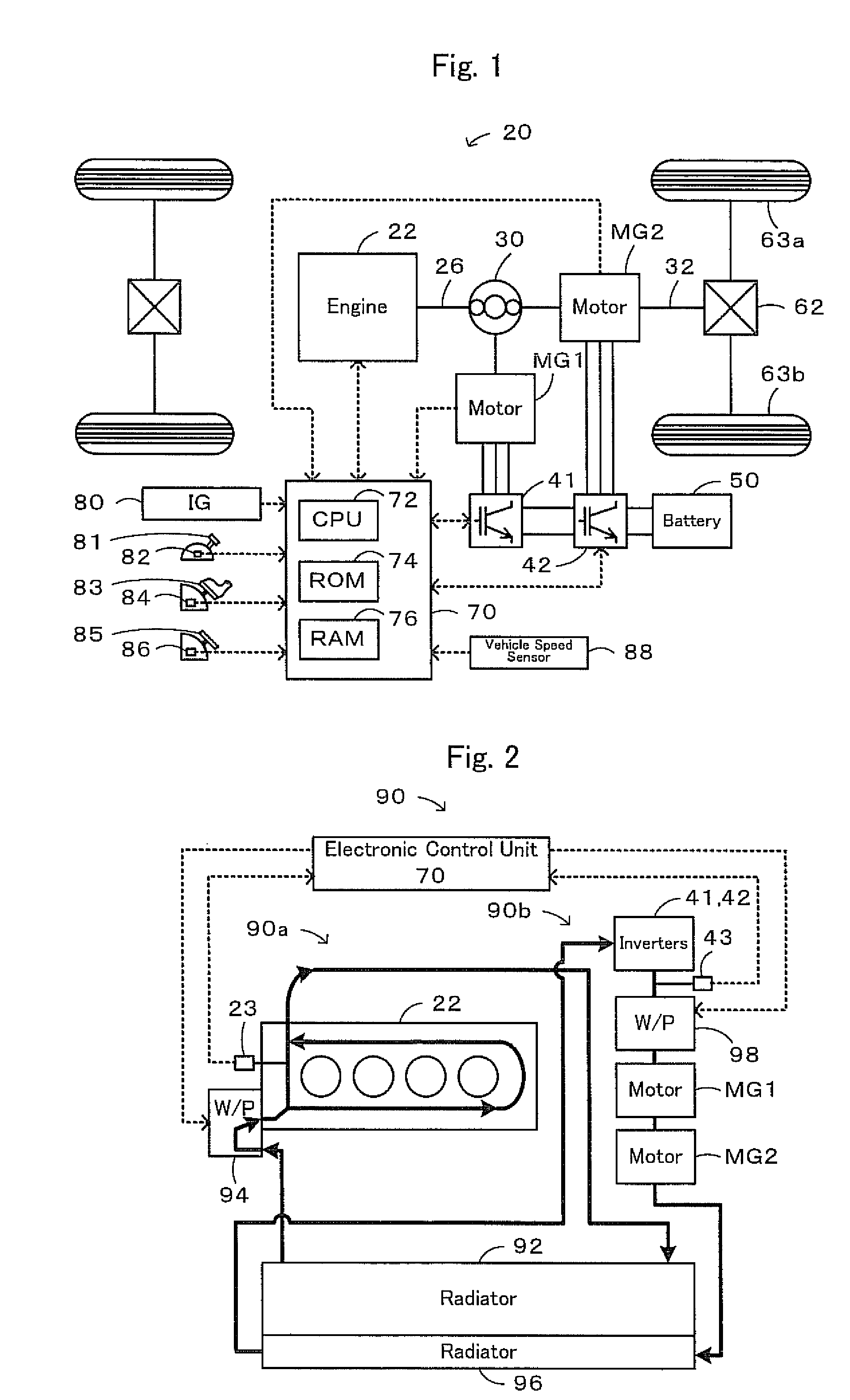
[0030]FIG. 1 is an explanatory view illustrating the schematic configuration of a hybrid vehicle 20 in accordance with one embodiment of the invention. As illustrated, the hybrid vehicle 20 of the embodiment includes an engine 22 or an internal combustion engine constructed to consume a hydrocarbon fuel, such as gasoline or light oil, and output power, and a planetary gear mechanism 30 constructed to have a carrier connected via a damper with a crankshaft 26 or an output shaft of the engine 22. The hybrid vehicle 20 also includes a motor MG1 structured as a synchronous generator motor to have a rotor connected to a sun gear of the planetary gear mechanism 30, and a motor MG2 structured as a synchronous generator motor to be connected with a ring gear of the planetary gear mechanism 30 and to have a rotor connected to a drive shaft 32 coupled with dri...


PUM


Abstract

A motor vehicle is equipped with an outside air introduction assembly 104 functioning to introduce the outside air into a radiator 92 in an engine cooling system during driving, as well as with an outside air introduction assembly 114 functioning to introduce the outside air into an engine 22 during driving. The motor vehicle is also equipped with shutter plates 106 capable of regulating the amount of the outside air to be introduced by the outside air introduction assembly 104, as well as with shutter plates 116 capable of regulating the amount of the outside air to be introduced by the outside air introduction assembly 114. The shutter plates 106 and the shutter plates 116 are individually actuated and controlled to increase the amount of the outside air to be introduced by the outside air introduction assembly 104 and the amount of the outside air to be introduced by the outside air introduction assembly 114 with an increase of temperature of cooling water detected as a cooling water temperature Twe in the engine cooling system. Such actuation and control assures the adequate cooling performances to cool down the cooling water by the radiator 92 and to cool down the engine 22.

Description

BACKGROUND OF THE INVENTION[0001]1. Technical Field[0002]The present invention relates to a motor vehicle and a control method of the motor vehicle. More specifically the invention pertains to a motor vehicle equipped with an internal combustion engine held in a storage space provided in a vehicle front portion, as well as to a control method of such a motor vehicle.[0003]2. Related Art[0004]One typically proposed structure of a motor vehicle includes a radiator provided on a front end of an engine room, a first radiator grill provided above a front bumper to be opposed to an upper portion on a front face of the radiator in a longitudinal direction of the vehicle, a second radiator grill provided in the front bumper to be opposed to a lower portion on the front face of the radiator in the longitudinal direction of the vehicle, shutter plates provided to adjust the opening area of the first radiator grill, and baffle plates provided to regulate the direction of the outside air introd...

Claims


Application Information

Patent Timeline
Patent Type & Authority Patents(United States)
IPC IPC(8): B60K11/08
CPCB60K11/085B60K6/445B60K6/48F01P7/12B60K6/365B60K1/02B60K2001/003B60L2240/425B60L2240/445B60W2510/0676B60W2510/087B60W2520/10Y02T10/6221Y02T10/6239Y02T10/642Y02T10/62Y02T10/64Y02T10/88
Inventor AMANO, TAKASHIKOTANI, TAKESHI
Owner TOYOTA JIDOSHA KK
Why Eureka
Try Eureka