
Metallic structure improvement for manufacturing electrical cabinets/panels

Inactive Publication Date: 2012-01-10
FRANCISQUINI MELQUISEDEC
View PDF30 Cites 40 Cited by
  • Summary
  • Abstract
  • Description
  • Claims
  • Application Information

AI Technical Summary

Benefits of technology

[0022]In the face of the abovementioned circumstances and with the objective of overcoming them the current invention was created, which in its final form defined a perfected structure where under one selfsame constructive characteristic it was possible to make the assembled version (structurally welded internally and externally throughout the perimeter's joints and corners) or the semi disassembled version (partially welded structure welded internally and externally at the cross section junctions for the width and height as well as the complementary assembly of the depth cross sections by means of screws), using a single cross section and still being able to support the mounting elements for the internal components with flexibility and safety, both for the assembly of the indoor and outdoor type electrical panels, including with a series of technical and practical advantages, among which these stand out:
[0023]a) the corner joints are characterised by their simple construction, technical efficiency and versatility, seeing that the connection that makes the joining of the two cross sections consists of a single piece (a square dowel from square steel), and it being used in the assembled as well as the semi-assembled version, and it may be easily manufactured from other materials, such as forged or cast steel etc.;
[0024]b) the use of a single cross section for the structure or, that is, the same cross section for the width as for the height and depth, besides facilitating manufacture also significantly reduces cost;
[0025]c) the manner of assembly in question associated to the transversal geometry of the cross section made it possible for a new technical effect of extreme importance, that is, all of the structure's assembled sides are symmetrically equal, which in a way favours the interlinking of one structure to the other on any of the other sides, including the top and bottom, consequently the current structure is modular and may be increased or decreased at any desired moment;
[0028]Finally, for some cases where the structure needs to be in one piece and not disassembled, the present improvement foresees a simplified and efficient constructive manner to achieve the aim, where only one steel dowel (connection for joining the corners) affords the means for welding on all the edges of the cross sections which are to be found on each corner of the structure, this welding is also extended to the corresponding faces of the referred to dowel, in such a manner that it comes to be an integral part of all the cross sections which are to be found in each corner, thus finalizing a constructive manner which considerably increases the rigidity of the structure.

Problems solved by technology

There currently are as has been said various types of structures and in most cases the structural effect obtained is reasonably satisfactory, nevertheless, with reference to seals, special technical operations are needed for its application, as well as presenting complicated industrial manufacturing in some cases due to the absence of technology, in others due to the need of complementary accessories as it happens for example in PI 8406283—mounting framework for a distribution cabinet deposited on 7 Dec. 1984, where the junction of the corners are obtained by a Zamak connection cast under pressure with three connection points (supposedly with the function of facilitating the assembly of the unit or maybe to offer better stability), nevertheless this type of solution has elevated costs and it also makes it impossible for the cross sections to be welded to the connectors as they are different materials, so welding is restricted to the points where the cross sections meet, which results in a lower mechanical stability for the structure although it is of the structurally welded type.
In these and other cases it is noted that the corners consist of a single piece made from steel, which enables welding between the connectors and cross sections, nevertheless this solution utilises two different cross sections for constructing the structure, one in the vertical assembly and the other on the horizontal, which is evidently, besides adding to the cost also interferes with the manufacturing of the unit, making it complicated.
Nevertheless this assembly concept competes to characterize various technical and practical disadvantages among which we may highlight: adds to the increased manufacturing cost; its transport and storage become substantially more difficult, seeing that the assembled structure requires a considerable amount of space to be occupied.
Under a second usual condition we may say that there are other types of disassembled structures, that is, structurally assembled with screws, where each one represents its respective construction characteristic, nevertheless, these existing solutions do not present satisfactory rigidity or mechanical stability for the destined applications.
Therefore in summary we can say that the inconveniences of the structures under the condition of the techniques are generated as a result of the manufacturing complexity, inefficiency for the more stringent applications, such as: Telecommunication and Medium Voltage, which requires the outdoor type (unsheltered use), incompatible mechanical stability and rigidity especially in the disassembled types.

Method used


Image

  • Metallic structure improvement for manufacturing electrical cabinets/panels
  • Metallic structure improvement for manufacturing electrical cabinets/panels
  • Metallic structure improvement for manufacturing electrical cabinets/panels

Examples


Embodiment Construction

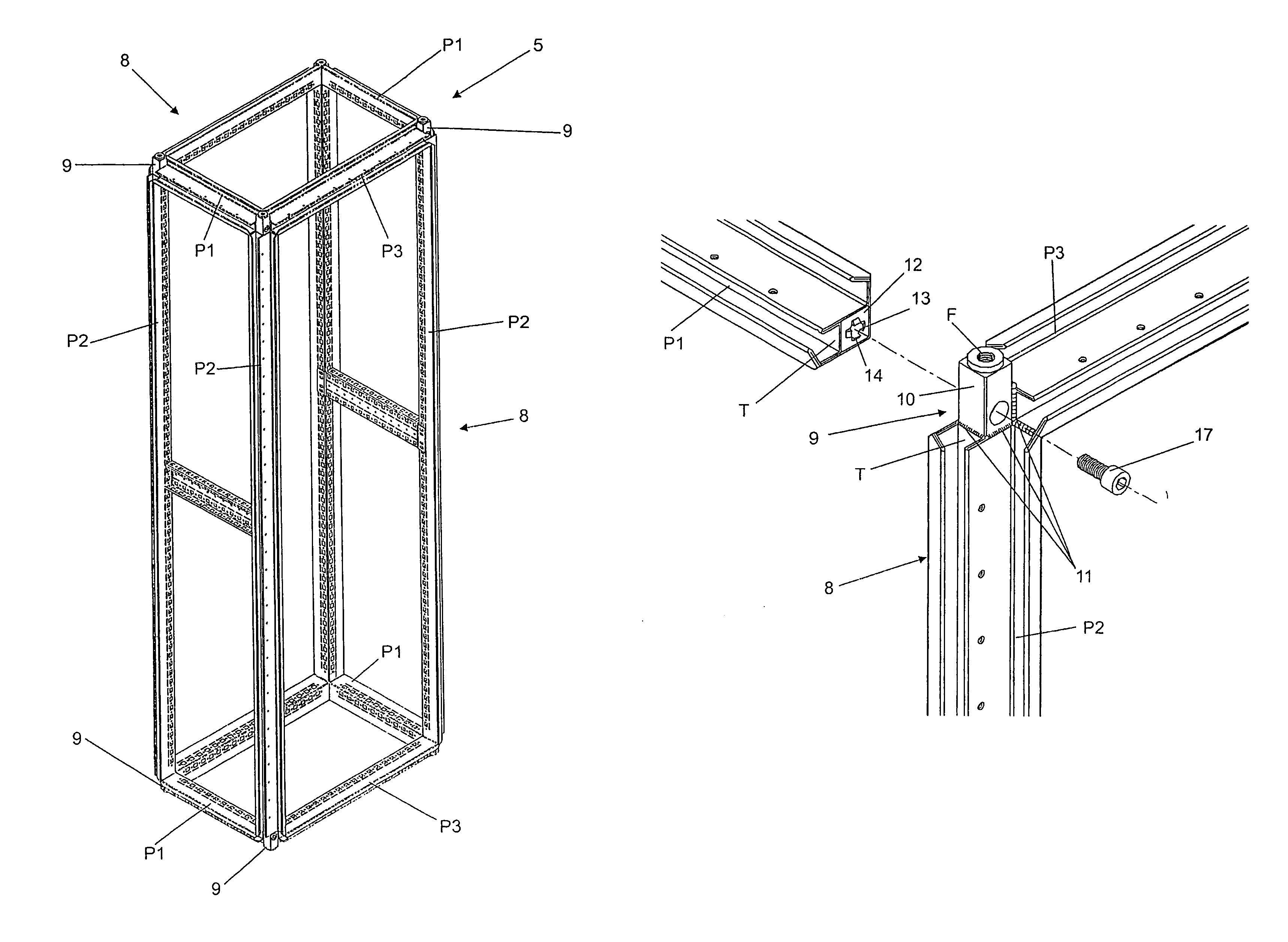
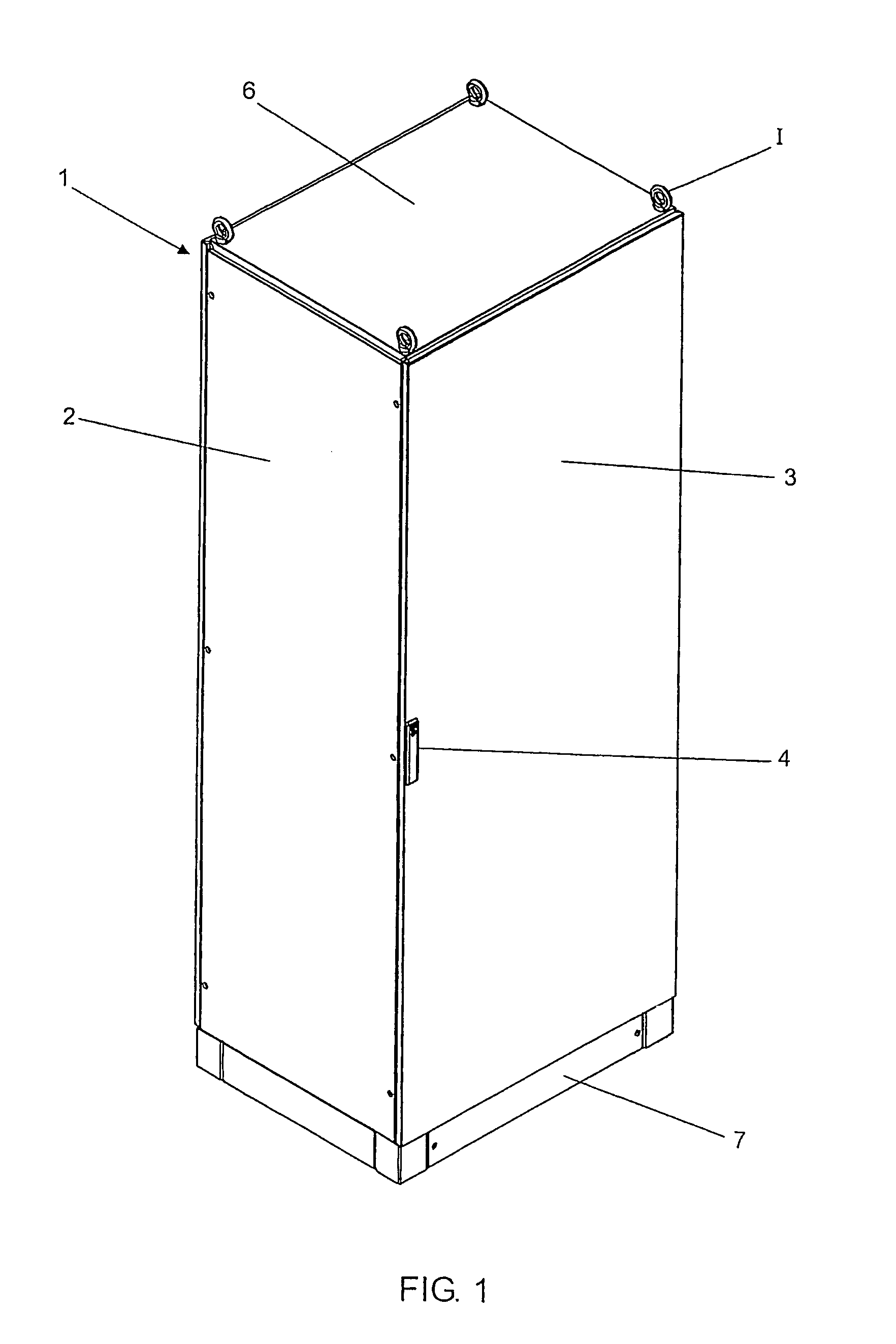
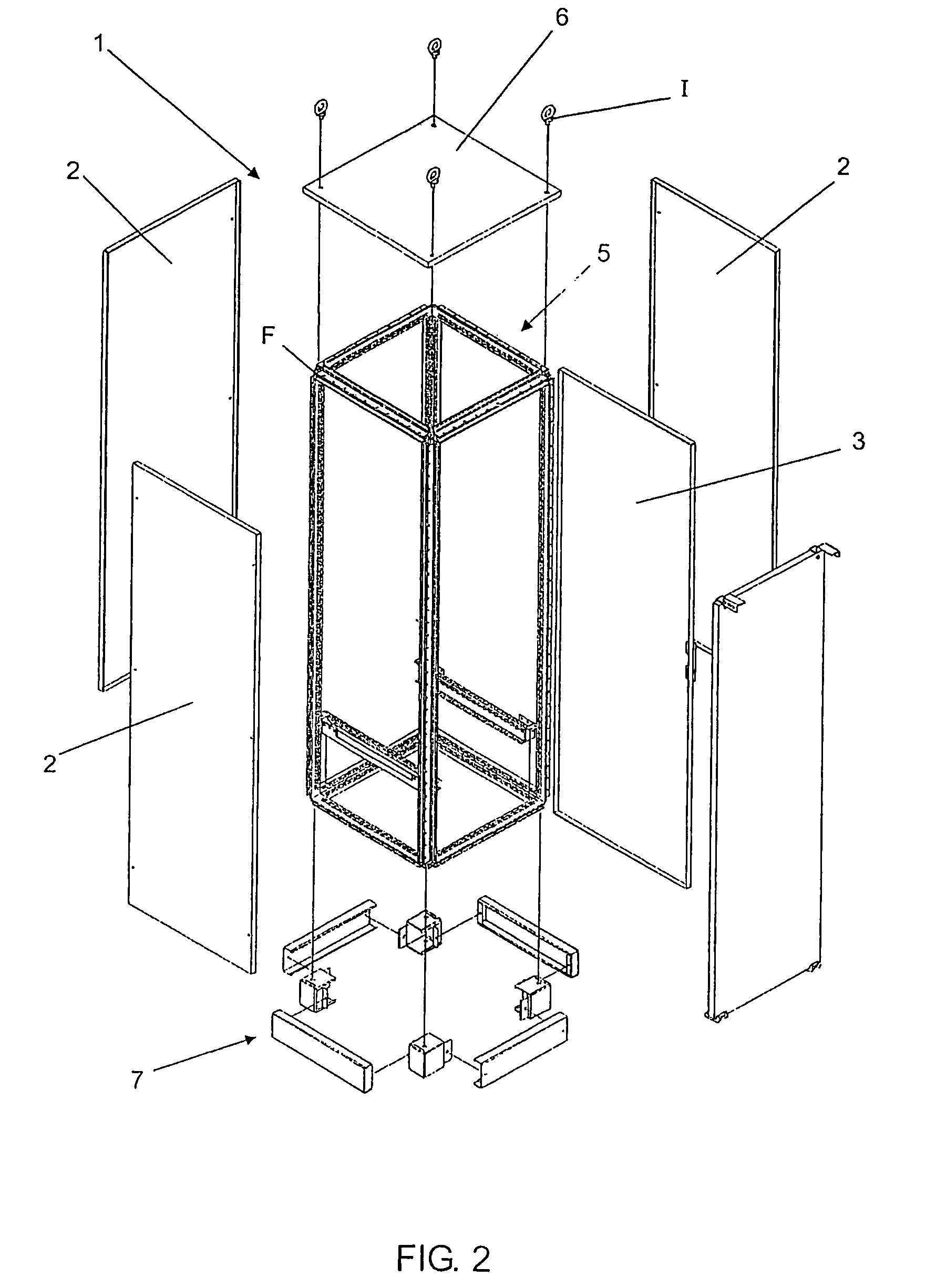
[0047]According to these illustrations and its details the current improvement to the metallic structure was particularly developed for mounting electrical cabinets or panels (1), generically shown in FIGS. 1 and 2, where only one type of example can be seen, which may be either indoor or outdoor, but, in both cases, the same is shown in the form of a metallic box with enclosed sides (2), including one or more tilting doors (3) with a lock (4). Such enclosures including the doors are normally manufactured from substantially thin metallic plates. In this manner, also as illustrated in FIG. 2, all electrical panels have an internal metallic cross section structure (5), through which can be seen that this structure, as the name itself says, constitutes the supporting means for the parts that make up the external walls from folded sheets, as it also constitutes the supporting and assembly means for the doors and its respective hinges as well as other accessories, such as: upper (6) and ...


PUM


Abstract

IMPROVEMENT TO THE METALLIC STRUCTURE FOR MANUFACTURING ELECTRICAL PANELS / CABINETS, enclosing a structure of metallic cross sections (5), with the device for supporting the parts making up the external walls from folded sheets, as well as constituting the device for supporting and mounting the doors with its respective hinges and other accessories, such as: the upper (6) and lower enclosure with the base (7) and other components, being that, still, same structure, although, on the inside, also configures the necessary mounts for distributing and assembling the different electrical and electronic components and devices; in the first construction version, the said structure (5) presented semi-assembled, where four of its uprights or four of its cross sections (P1) are completely free while all the other cross sections are rigidly integrated into two equal rectangular frames (8) which form the two opposite sides of the said structure (5) and therefore at the corner point of the junction of each rectangular frame (8) there is a complementary device (9) cooperating for the interlinking at 90° between two adjacent cross sections (P2) and (P3) of each frame (8), as also this selfsame device presents the mechanism so that the extremities of the other cross sections (P1) may be coupled between the corners of the rectangular frames (8), thus forming the structure (5).

Description

FIELD OF INVENTION[0001]This invention refers to a metallic structure assembled with a combination of different components, including special cross sections, notably of the type formed in an extruder, defining the structure with a constructively differentiated concept from which some technical and practical improvements are obtained, including quality with cost reduction.[0002]This type of structure in a general manner is normally used in the most varied of cabinet types also known as electrical panels, which in reality are cabinets with doors and closed off sides used to house a very large variety of electrical and electronic components and devices.BACKGROUND[0003]As it is common knowledge of those qualified in this technique, currently there are different types of electrical panels also called frames or cabinets, designed to house the most varied of components in the most varied of activity fields also including the telephony sector.[0004]Therefore under different electrical distr...

Claims


Application Information

Patent Timeline
IPC IPC(8): A47G29/00A47B47/02H02B1/01H02B1/30H05K7/18
CPCH02B1/301H02B1/013H02B1/014H02B1/30H02B1/01
Inventor FRANCISQUINI, MELQUISEDEC
Owner FRANCISQUINI MELQUISEDEC
Features
  • Generate Ideas
  • Intellectual Property
  • Life Sciences
  • Materials
  • Tech Scout
  • Unparalleled Data Quality
  • Higher Quality Content
  • 60% Fewer Hallucinations
Learn More