Method for recovering electrical energy in vehicle with regenerative braking

a technology of regenerative braking and electrical energy, which is applied in the direction of electric vehicles, electrodynamic brake systems, dc motor stoppers, etc., can solve the problems of premature ageing, insufficient management of transitory energy given off by regenerative braking, and inconvenient loading of lead/acid batteries normally used in motor vehicles, etc., to achieve maximum performance or electrical power

Active Publication Date: 2012-01-10
VALEO EQUIP ELECTRIC MOTEUR
View PDF12 Cites 1 Cited by
  • Summary
  • Abstract
  • Description
  • Claims
  • Application Information

AI Technical Summary

Benefits of technology

[0031]The invention can be used to particular advantage in combination with the bi-voltage system known as 14+X. This architecture comprises two independent electrical circuits, one of which, the 14+X, by virtue of its technology, is capable of functioning at a variable voltage. This enables new control strategies to be employed in a particularly effective manner in order to maximise the performance or the electrical power that is supplied during the regeneration stage.

Problems solved by technology

Increasing the power of the alternators and the storage capacity of the battery involves a number of drawbacks in terms of costs, space, a problem of installation in a difficult location (under the bonnet) and also of weight.
Furthermore, the lead / acid batteries normally used in motor vehicles are not suitable for loading with very high current levels during a sufficient period to allow part of the energy given off by a braking device to be recovered.
In this type of device, the management of the transitory energy given off by regenerative braking is not efficient enough to ensure that the voltage circulating in the electrical distribution circuit is properly regulated and the repeated charging of the lead / acid battery has an effect of prematurely ageing the latter.
When the driver starts the engine, the super-capacitor discharges and unless the braking system is operated to any great degree, the amount of electrical energy that is recovered is insufficient to fully charge the super-capacitor.

Method used


Image

  • Method for recovering electrical energy in vehicle with regenerative braking
  • Method for recovering electrical energy in vehicle with regenerative braking
  • Method for recovering electrical energy in vehicle with regenerative braking

Examples


Embodiment Construction

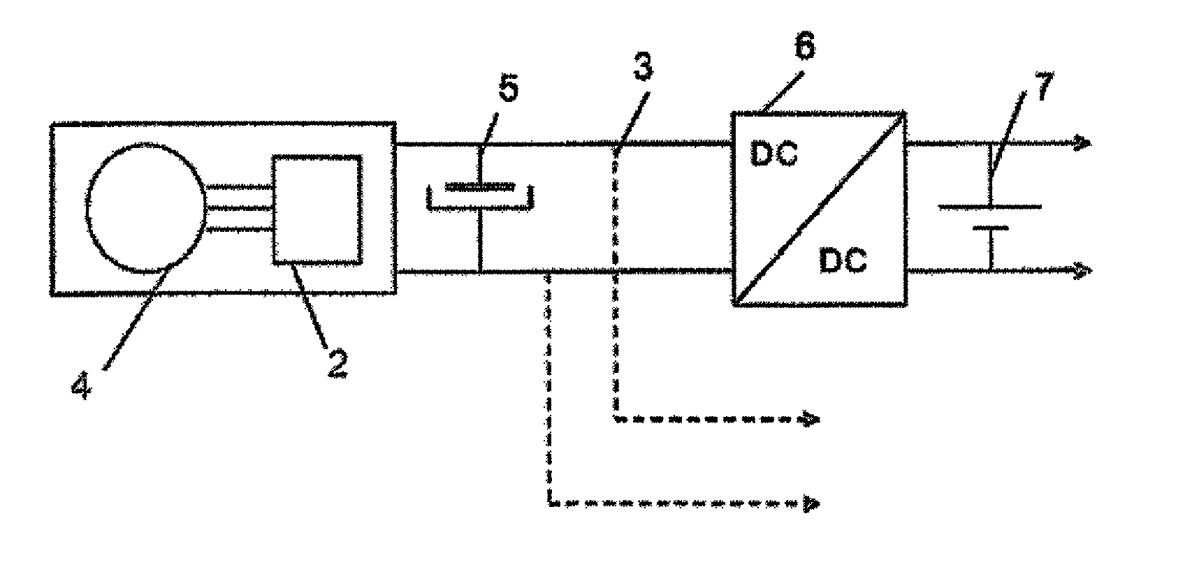
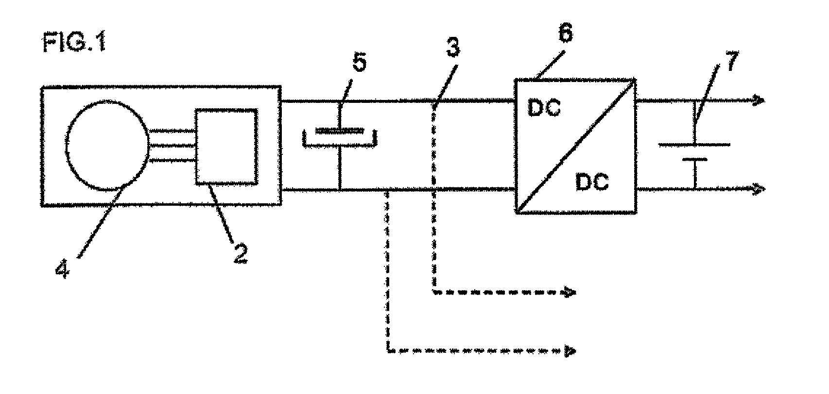
[0037]In a particular embodiment, FIG. 1 contains a schematic representation of an electrical energy regeneration system installed in a motor vehicle. An AC / DC converter 2 is connected firstly to a continuous bus 3 and secondly to a rotary electrical machine 4. The AC / DC converter 2 and the machine 4 are of the multi-phase type, typically of the three-phase type. The AC / DC converter 2 here is an electrical device of a voltage rectifier type enabling the three-phase AC voltages supplied by the machine 4, operating in an AC mode, to be converted into direct current. In other embodiments of the invention in which the machine 4 is reversible and functions as a starter-alternator, the AC / DC converter 2 is also reversible and comprises a wave mode to supply the machine 4 with three-phase voltages, which, is in this case an electrical machine or a starter.

[0038]The bus 3 comprises a reservoir 5 of electrical energy. This reservoir is a super-capacitor in this particular embodiment. In this...


PUM


Abstract

Method for recovering electrical energy in a vehicle with regenerative braking is used in a vehicle equipped for this purpose with an electrical capacitance device to store electrical energy supplied by a rotary electrical machine of the vehicle during regenerative braking operation. A choice is made, on the basis of the initial rotational speed of the rotary electrical machine to apply an energy recovery stratagem from at least the following two: —a first energy recovery strategy that favors high power supplied by the rotary electrical machine; and—a second energy recovery strategy that favors high efficiency of the rotary electrical machine.

Description

CROSS-REFERENCE TO RELATED APPLICATIONS[0001]This application relates to International Application No. PCT / FR2007 / 051373 filed Jun. 4, 2007 and French Patent Application No. 0652675 filed Jun. 27, 2006, of which the disclosures are incorporated herein by reference and to which priority is claimed.[0002]The present invention is applied particularly to advantage in the motor vehicle sector. It relates in particular to a process for the recovery of electrical energy in a motor vehicle equipped with a regenerative braking system.BACKGROUND OF THE INVENTION[0003]1. Field of the Invention.[0004]When a motor vehicle is braked, kinetic energy is dissipated into the brake disks in the form of heat. In order to recover this kinetic energy, the current state of the art provides for regenerative braking systems. Devices of this type are able to recover the kinetic energy given off during braking and to convert this into electrical energy.[0005]2. Description of Related Art.[0006]In a motor vehi...

Claims


Application Information

Patent Timeline
Patent Type & Authority Patents(United States)
IPC IPC(8): B60W10/08
CPCB60L7/16H02J7/1446H02J7/1492Y02T10/92Y02T10/7022Y10T477/322Y10T477/24H02J7/345Y02T10/70
Inventor MASFARAUD, JULIENDOFFIN, HUGUES
Owner VALEO EQUIP ELECTRIC MOTEUR
Why Eureka
Try Eureka