Spindle gripping device and method

a technology of a gripping device and a pindle, which is applied in the direction of transportation and packaging, transportation and packaging, and work transportation apparatus, etc. it can solve the problems of reducing the efficiency of the system, so as to facilitate the overall assembly process.

Inactive Publication Date: 2012-01-10
HONDA MOTOR CO LTD
View PDF22 Cites 14 Cited by
  • Summary
  • Abstract
  • Description
  • Claims
  • Application Information

AI Technical Summary

Benefits of technology

[0009]According to another aspect of the present invention, the gripper tool is used to facilitate the overall assembly process by receiving a workpiece into the CNC machine and outputting a machined workpiece from the CNC machine.

Problems solved by technology

As the workpiece must be held by the positioning block along at least one surface, the held surfaces are not available to the drilling work tool.
Placing the workpiece into the positioning block, repositioning the workpiece during operation, and removing the workpiece upon conclusion of the machining operation all reduce the efficiency of the system.
Manpower is flexible, however is also relatively expensive and can make errors in handling parts.
Robots are accurate, but expensive.
Gantry loaders are also expensive and must be custom designed.

Method used


Image

  • Spindle gripping device and method
  • Spindle gripping device and method
  • Spindle gripping device and method

Examples


Embodiment Construction

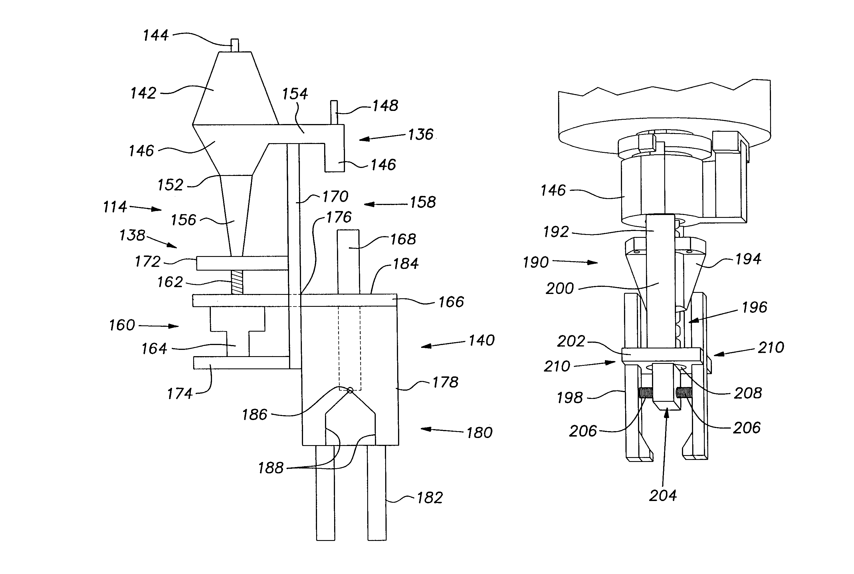
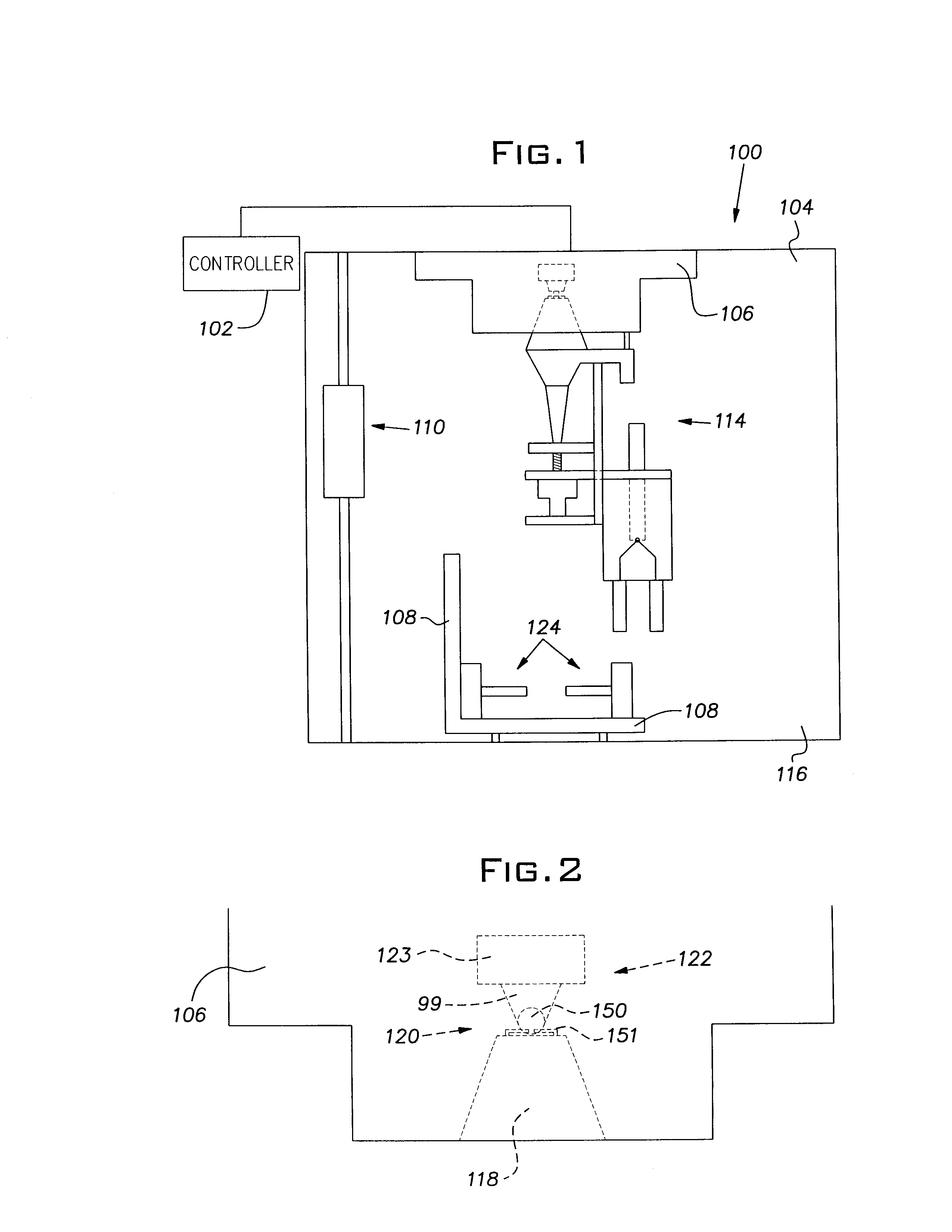
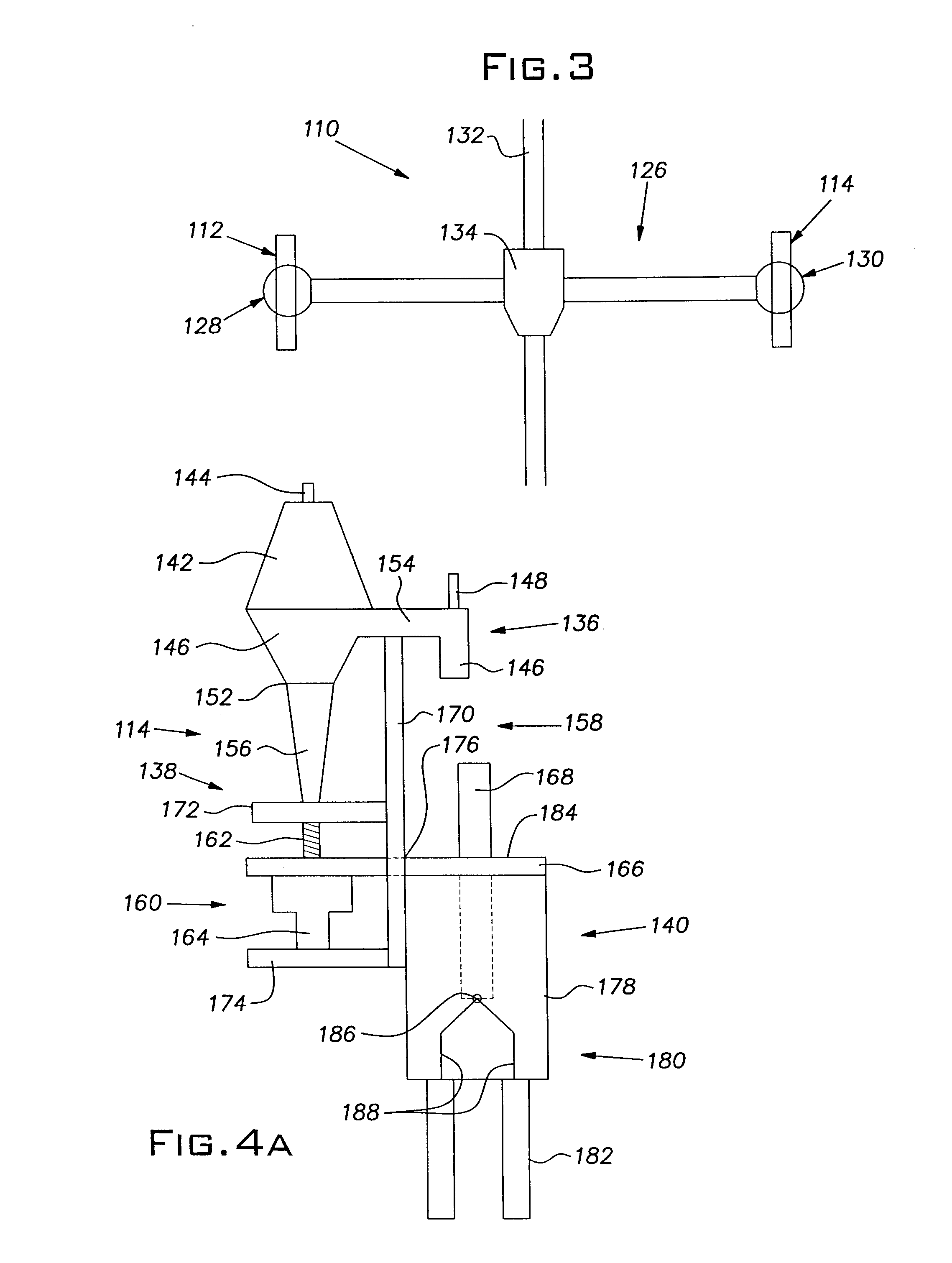
[0018]With reference to FIG. 1, a CNC machine 100 includes a controller 102 and a work envelope 104. The work envelope 104 has a top wall, a bottom wall, and two side walls cooperating to form a generally rectangular space that is accessible from at least one side via a selectively openable safety door 116. The work envelope 104 receives a spindle 106, a part mounting block 108, an automatic tool changer 110, a drill tool 112, and a gripper tool 114. As the CNC machine 100 described herein performs a cutting or drilling operation, it is important that the walls of the work envelope 104 and the safety door 116 are made of a strong material which will prevent any metal shards from escaping the work envelope 104 during machining. The work envelope 104 further defines a communication means to allow the controller 102 to connect with the CNC machine 100 components disposed within the work envelope 104.

[0019]The controller 102 is connected with, and provides operating instructions to, the...


PUM

PropertyMeasurementUnit
timeaaaaaaaaaa
rotational forceaaaaaaaaaa
flexibleaaaaaaaaaa

Abstract

A spindle gripping device and method for use in a CNC machine for re-orienting a workpiece. The gripping device includes an attachment portion, a translational driver, and a gripping portion. The attachment portion mechanically attaches the gripping device to a spindle of the CNC machine, and allows a transfer of the rotation of the spindle to the gripping device. The translational driver translates the input rotational force into a linear movement. The gripping portion uses the linear movement to open and close claws of the gripping device. A controller monitors and controls the operation of the CNC machine, so as to control an exchange of the working tool with the gripping device, and to control actuation and subsequent movement of the gripping device to reposition the workpiece into a desired orientation.

Description

BACKGROUND OF THE INVENTION[0001]In a manufacturing setting, Computer Numerical Control (CNC) machines are commonly used to precisely work components. Specifically, a computer controller drives a machine tool to perform a cutting operation within a work envelope of the machine. The use of CNC machines has resulted in considerable improvements in the consistency and quality of machined parts. Further, CNC automation has reduced the time required to change the machine to produce different components.[0002]CNC machines are generally used for drilling or tapping operations, such as an operation of drilling holes into an engine block. A typical CNC machine will have a work envelope within which the cutting operation is performed, a mounting block for holding the part to be operated upon, a spindle which generates a rotational force, a work tool for performing the drilling function, and a controller for instructing machine operation. In operation, a workpiece is placed in the mounting blo...

Claims


Application Information

Patent Timeline
Patent Type & Authority Patents(United States)
IPC IPC(8): B23Q3/157B23B13/12B23Q7/04B23Q3/155
CPCB23B39/06B23Q7/045B23Q2220/008Y10T483/176Y10S483/902Y10T483/16Y10T483/17Y10S483/901B23Q2230/002
Inventor BUUS, DAMON
Owner HONDA MOTOR CO LTD
Why Eureka
Try Eureka