
Positive resist composition and pattern forming method using the same

a composition and composition technology, applied in the field of positive resist composition and pattern forming method using the same, can solve the problems of disadvantageous narrowing of the process margin at the actual pattern formation, and the inability to meet all performances in terms of high sensitivity, so as to enhance the performance at fine patterning, high sensitivity, and positive resist composition

Inactive Publication Date: 2012-01-10
FUJIFILM CORP
View PDF12 Cites 2 Cited by
  • Summary
  • Abstract
  • Description
  • Claims
  • Application Information

AI Technical Summary

Benefits of technology

An object of the present invention is to solve the problems in the technology for enhancing the performance at fine patterning of a semiconductor device, where actinic ray or radiation, particularly, KrF excimer laser light, electron beam, X ray or EUV light is used, and provide a positive resist composition satisfying all performances in terms of high sensitivity, high resolution, good defocus latitude depended on line pitch, line width roughness and exposure margin, and a pattern forming method using the composition.

Problems solved by technology

The defocus latitude depended on line pitch as used herein means a difference in the pattern dimension between a high density portion and a low density portion of a resist pattern and when this difference is large, the process margin is disadvantageously narrowed at the actual pattern formation.
Furthermore, also in the lithography using KrF excimer laser light, how to satisfy all of high sensitivity, high resolution and good defocus latitude depended on line pitch is an important problem, and this problem needs to be solved.
However, by any combination of these techniques, it is impossible at present to satisfy all performances in terms of high sensitivity, high resolution, good defocus latitude depended on line pitch, line width roughness and exposure margin in the ultrafine region.

Method used


Image

  • Positive resist composition and pattern forming method using the same
  • Positive resist composition and pattern forming method using the same
  • Positive resist composition and pattern forming method using the same

Examples


synthesis example 1

Synthesis of Resin (R-101)

After dissolving 36 g of a (4-vinylphenol)-(4′-vinyl-trifluoromethylacetophenone oxime 2,4,6-triisoprpylbenzene sulfonate) copolymer (compositional ratio: 95 / 5, weight average molecular weight: 8,900) in 200 mL of THF, 6 g of ethyl vinyl ether and 0.05 g of p-toluenesulfonic acid were added to the reaction solution and allowed to react at room temperature for 3 hours. Thereto, 0.1 g of triethylamine was added and after stirring for 10 minutes, the reaction solution was reprecipitated in 2 L of distilled water. The precipitated white powder was collected by filtration and then dried at 40° C. under reduced pressure.

The compositional ratio of the polymer determined from C13NMR was 65 / 30 / 5. Also, the weight average molecular weight determined by GPC was 9,200 in terms of standard polystyrene.

The other resins were synthesized in the same way.

The compositional ratio (molar ratio of repeating units, corresponding to repeating units from the left), weight average ...


PUM

PropertyMeasurementUnit
carbon numberaaaaaaaaaa

Abstract

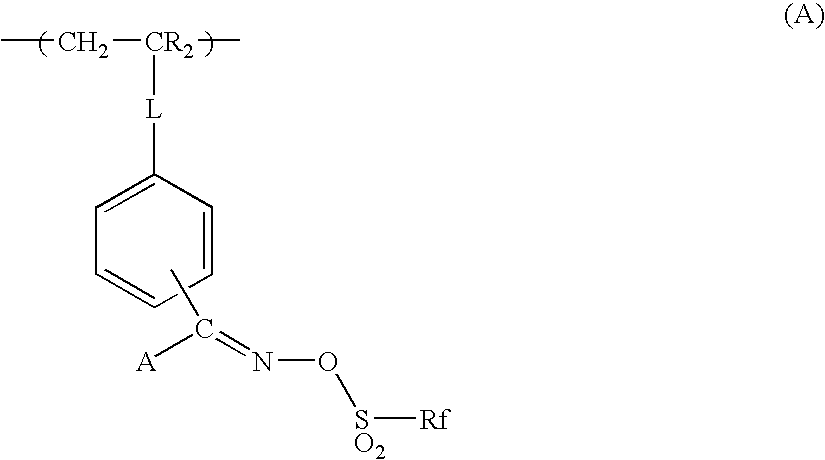
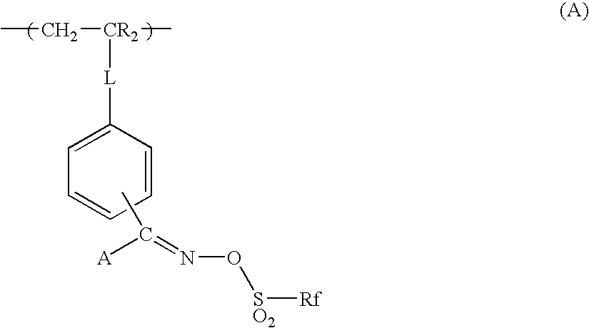
A positive resist composition, includes: (A) a resin having a repeating unit represented by formula (A) as defined in the specification, which decomposes under an action of an acid to increase a solubility of the resin (A) in an alkali developer; and a pattern forming method uses the composition.

Description

BACKGROUND OF THE INVENTION1. Field of the InventionThe present invention relates to a positive resist composition suitable for use in the ultramicrolithography process such as production of VLSI or high-capacity microchip or in other photofabrication processes, and a pattern forming method using the same. More specifically, the present invention relates to a positive resist composition capable of forming a high-resolution pattern by using KrF excimer laser light, electron beam, X ray, EUV light or the like, and a pattern forming method using the same. That is, the present invention relates to a positive resist composition suitably usable for fine processing of a semiconductor device, where KrF excimer laser light, electron beam, X ray or EUV light is used, and a pattern forming method using the same.2. Description of the Related ArtIn the process of producing a semiconductor device such as IC and LSI, fine processing by lithography using a photoresist composition has been conventio...

Claims


Application Information

Patent Timeline
Patent Type & Authority Patents(United States)
IPC IPC(8): G03F7/039G03F7/028C08F12/26C08F12/30
CPCG03F7/0045G03F7/0046G03F7/0392
Inventor MIZUTANI, KAZUYOSHI
Owner FUJIFILM CORP
Learn More