Plant for the production of electric power from the movement of waves

a technology of electric power and plant, which is applied in the direction of water power plants, sea energy generation, couplings, etc., can solve the problems of unsatisfactory efficiency and very complex production of plants, and achieve the effect of optimal operating efficiency

Active Publication Date: 2012-01-10
BOZANO ENRICO
View PDF18 Cites 18 Cited by
  • Summary
  • Abstract
  • Description
  • Claims
  • Application Information

AI Technical Summary

Benefits of technology

[0004]The object of the present invention is therefore to provide a plant for producing electric power which is economically advantageous, which is simple in terms of its constructional design and which ensures an optimum operating efficiency.

Problems solved by technology

These systems, however, have often proved to be very complex to produce and their efficiency does not achieve fully satisfactory results.

Method used


Image

  • Plant for the production of electric power from the movement of waves
  • Plant for the production of electric power from the movement of waves
  • Plant for the production of electric power from the movement of waves

Examples


first embodiment

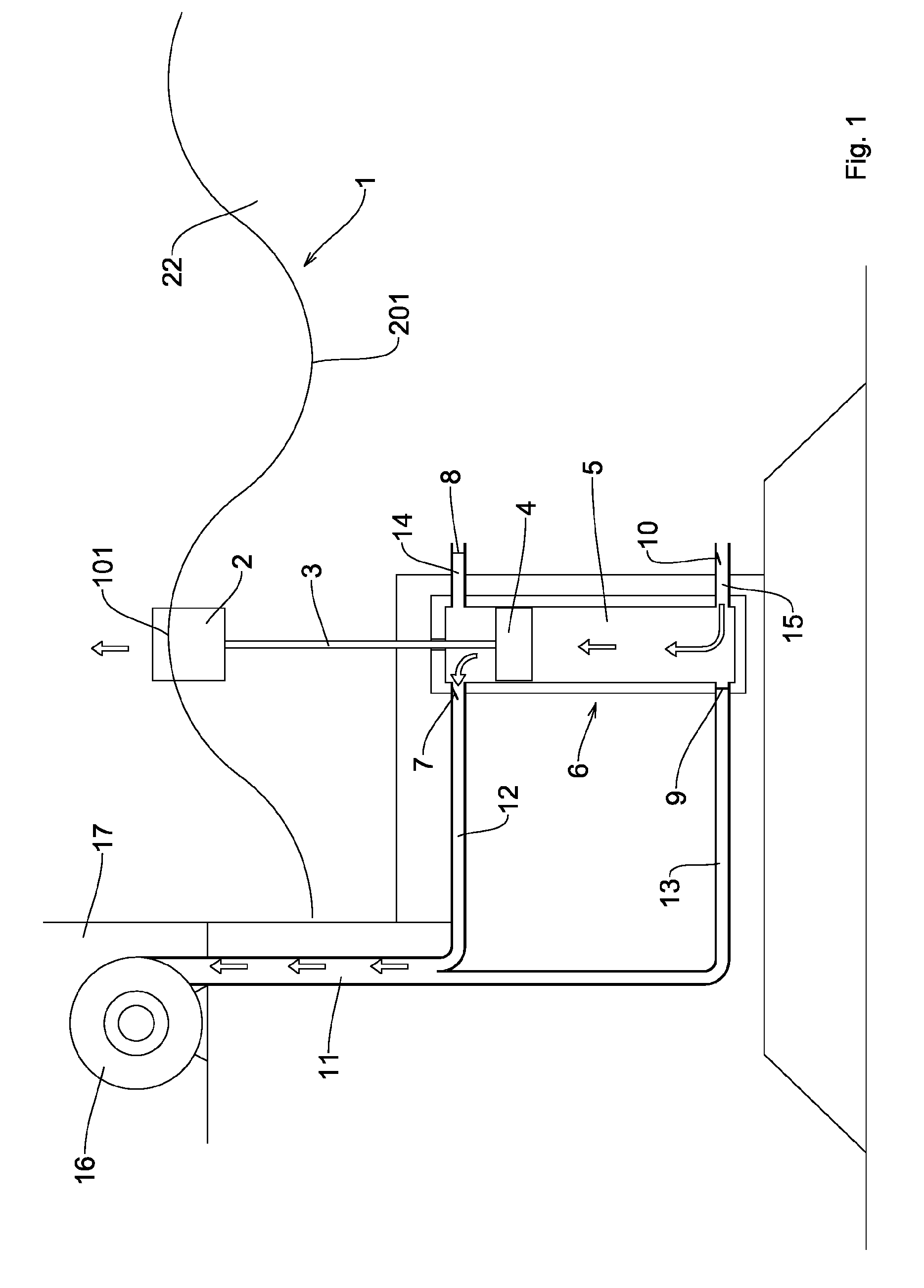
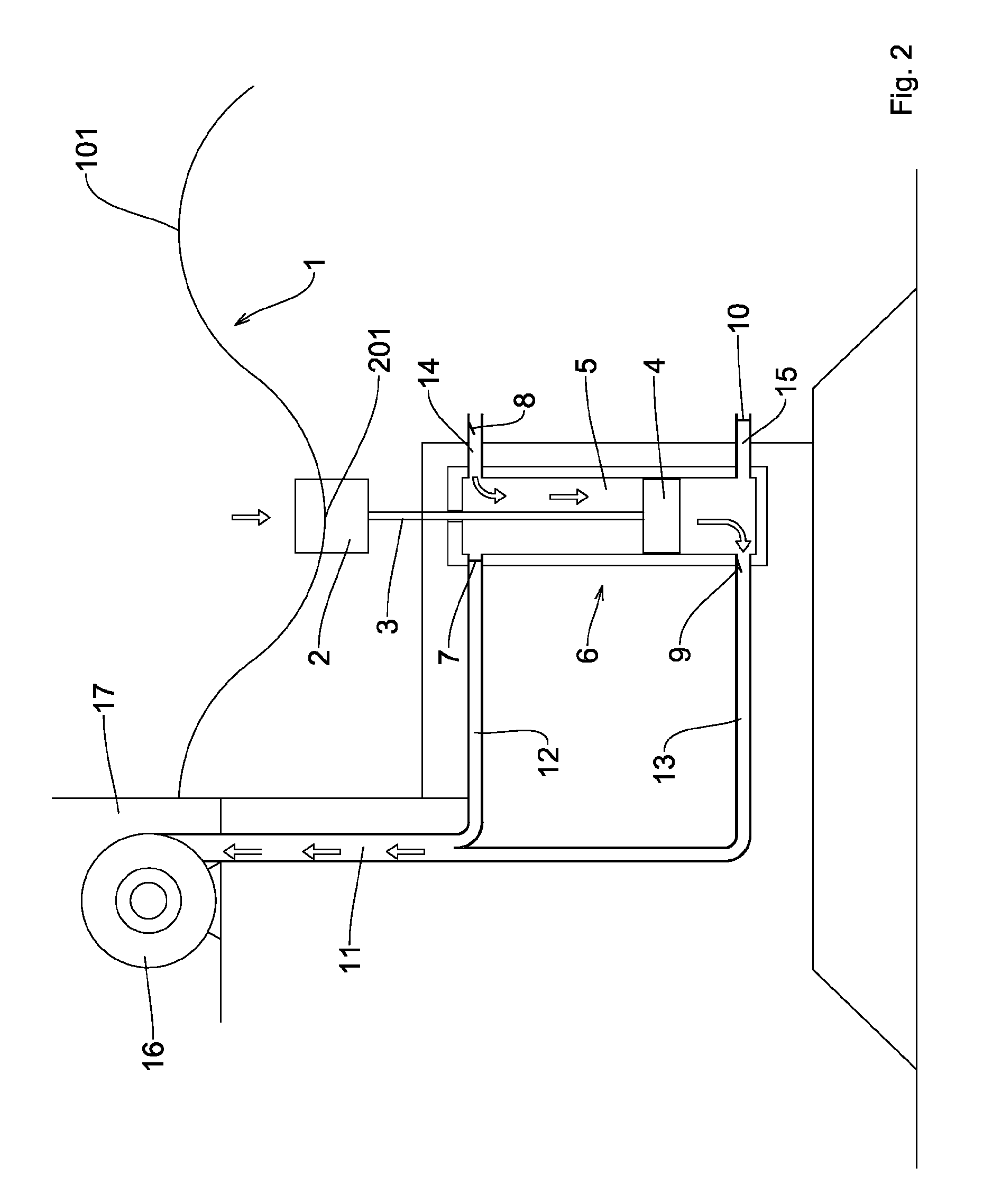
[0015]In the figure, the float 2 of the present plant, according to this first embodiment of the invention, is situated at the top of a crest 101 of the sea wave 1: the piston 4, joined to this float 2 by means of the rod 3, will have therefore performed a movement from the bottom upwards inside the cylinder 5 in order to reach the position shown, causing opening of the valve 10 which allows the entry of a certain amount of water through the duct 15 inside this cylinder 5 into the zone underneath this piston 4. After completion of the rising movement of the float 2 as far as the crest 101 of the wave 1, and therefore the piston 4 into the vicinity of the cylinder 5, the descending movement of this float will start, as can be seen in FIG. 2 of the accompanying drawings, until it reaches the trough 201 of this wave 1. During the downward movement the float 2 will push the piston 4 downwards so that it reaches, in the region of the trough 201 of the wave 1, a position close to the bott...

second embodiment

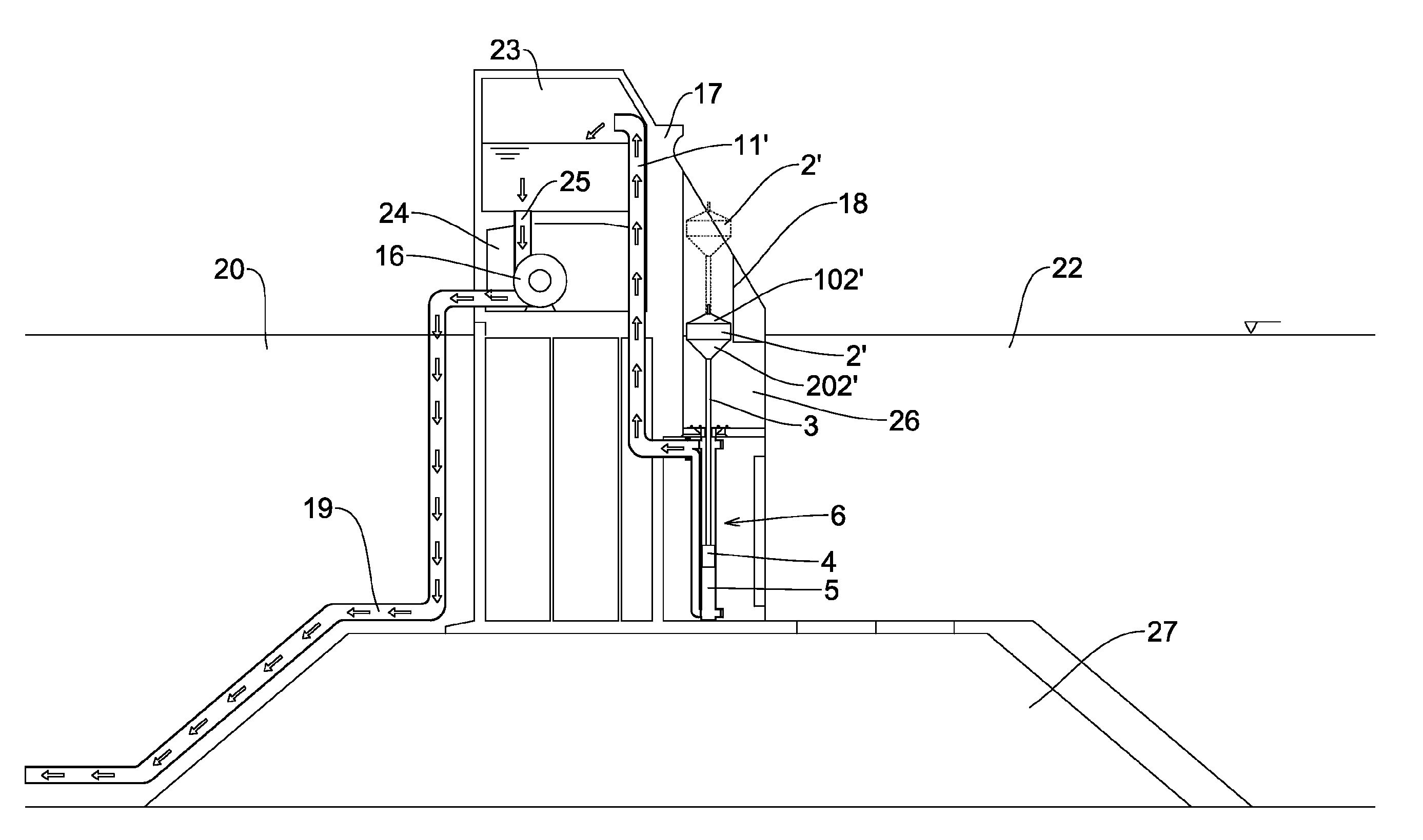
[0017]FIG. 3 shows the present plant. In this case the offshore dam 17 comprises a seat 18, which is preferably cylindrical, inside which the float 2′ may slide, said float, as can be seen, having an upper section 102′ and a lower section 202′ which are substantially conical or frustoconical, so as to facilitate the upward and downward movement thereof, also in the case of sea waves of smaller amplitude. Underneath this float 2′, the offshore dam 17 has, formed therein, an expansion chamber 21 for the incoming sea wave, which communicates with the section 22 of seawater outside the offshore dam 17 and is provided with a suitable water inlet opening situated above the hydraulic pump 6. As can be seen, the hydraulic pump 6 is similar to that shown in the previous embodiment, while the duct 11 conveys the water delivered by this pump 6 to the turbine 16 and from here to a further recirculation duct 19. The water used in the turbine 16 enters into this recirculation duct 19 and may be u...


PUM


Abstract

A plant for producing electrical power from the movement of waves. An offshore dam has a fixed generally vertical surface which is located in open water having wave movement and located vertically at the water surface. A submerged part which is fixed relative to the dam has an opening below the waves and in close proximity to the plane of the vertical surface to receive sea water. A force exerting structure such as a hydraulic pump or a thrust arrangement receives the water through the opening and forces that water through a one-way valve beyond which it is led to a turbine for producing electric power.

Description

FIELD OF THE INVENTION[0001]The present invention relates to a plant for producing electric power from the movement of waves.BACKGROUND OF THE INVENTION[0002]As is known, at present various systems for producing electric power from the movement of waves are known, said systems, for example, being able to make use of the fluctuating movements of sea waves in order to operate devices which are situated, for example, on a wall against which these waves suitably connected to electric power generators collide. Another type of system for obtaining power from the movement of waves consists in complex apparatus provided with buoys anchored to the seabed and completely submerged: the continuous motion of the waves imparts a continuous movement to these buoys which are anchored to the seabed and which in turn are connected to floating cylinders co-operating with actuator means connected to electric generators. The principle of these systems is therefore essentially that of causing the movemen...

Claims


Application Information

Patent Timeline
Patent Type & Authority Patents(United States)
IPC IPC(8): F03B13/18
CPCF03B13/145F03B13/147F03B13/187F04B35/004F05B2240/95F05B2250/5011Y02E10/38Y02E10/30
Inventor BOZANO, ENRICO
Owner BOZANO ENRICO
Why Eureka
Try Eureka