Light sources incorporating light emitting diodes

a technology of light-emitting diodes and light-emitting diodes, which is applied in the direction of lighting and heating apparatus, process and machine control, instruments, etc., can solve the problems of short life expectancy, short less desirable light generated by fluorescent lighting systems. , to achieve the effect of improving usability and aesthetic qualities of light, improving color rendering, and less fragil

Inactive Publication Date: 2012-01-10
ILUMISYS
View PDF147 Cites 189 Cited by
  • Summary
  • Abstract
  • Description
  • Claims
  • Application Information

AI Technical Summary

Benefits of technology

[0006]The present invention includes replacements for conventional light sources such as fluorescent light tubes and incandescent light bulbs that overcomes the disadvantages of the prior art. Specifically, the invention comprises various light sources incorporating light emitting diodes. Light emitting diodes can be manufactured that have superior color rendering than most fluorescent lamps, which improves the usability and aesthetic qualities of the light. In addition, light emitting diodes are less fragile than incandescent and fluorescent lighting components.

Problems solved by technology

On the other hand, the light generated by fluorescent lighting systems is less desirable in many applications than incandescent lighting systems because conventional fluorescent lighting systems generally produce a cooler light that has more blue and less red than incandescent lighting systems.
Fluorescent light tubes, in particular, have a short life expectancy, are prone to fail when subjected to excessive vibration, consume high amounts of power, require a high operating voltage and include several electrical connections that reduce reliability.
Conventional ballasts are highly prone to fail when subjected to excessive vibration.

Method used


Image

  • Light sources incorporating light emitting diodes
  • Light sources incorporating light emitting diodes
  • Light sources incorporating light emitting diodes

Examples


Embodiment Construction

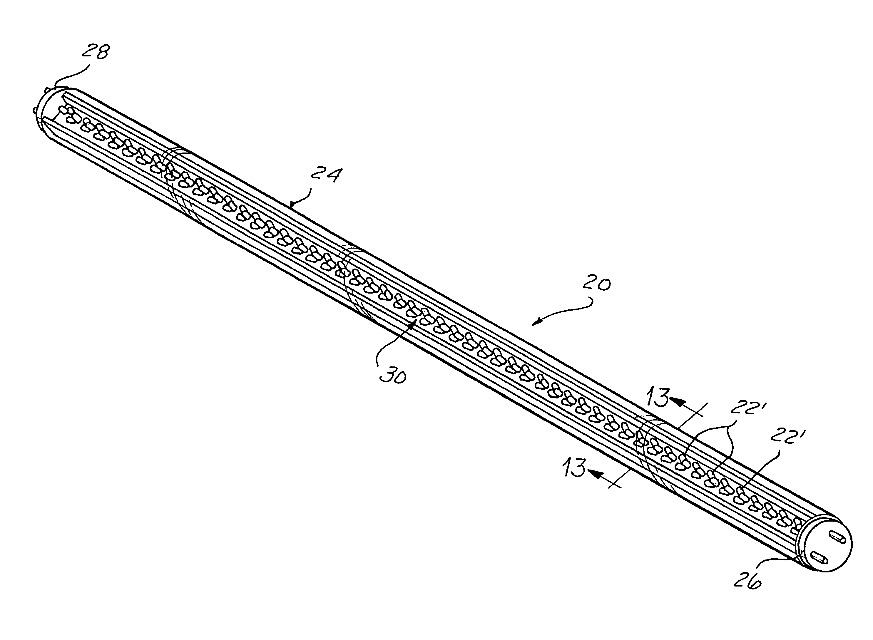
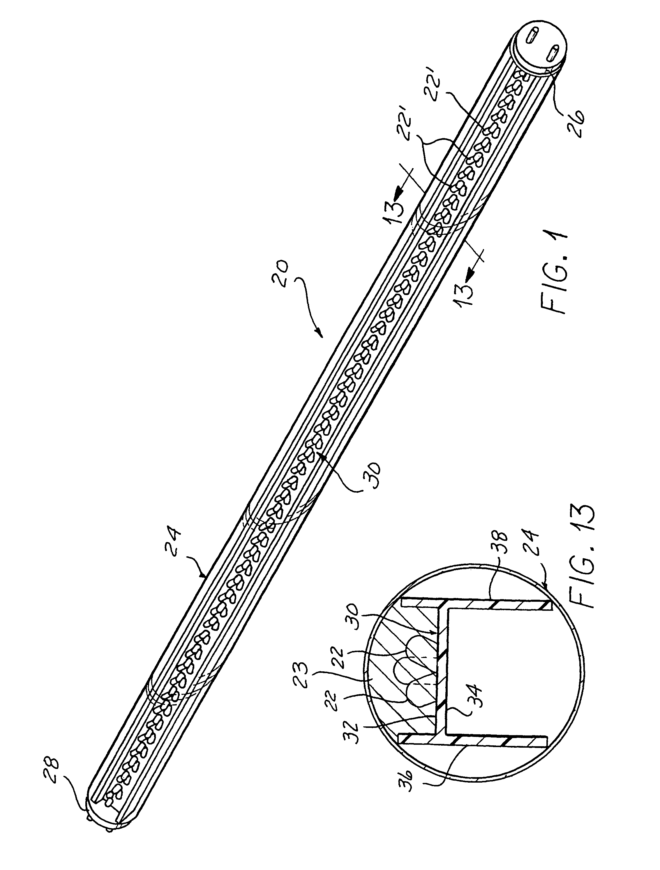
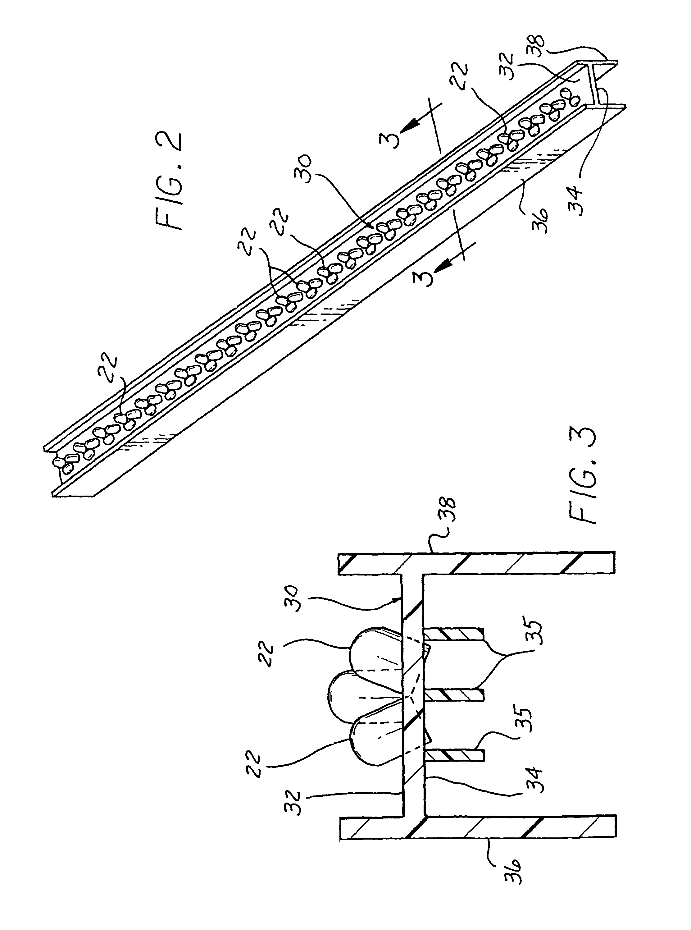
[0027]FIG. 1 is a perspective view showing a light source according to the invention in the form of a light tube 20. In accordance with a first embodiment of the invention, the light tube 20 is illuminated by LEDs 22 packaged inside the light tube 20. The light tube 20 includes a cylindrically shaped housing portion 24 having a pair of end caps 26 and 28 disposed at opposite ends of the housing portion 24. Preferably, the housing portion 24 is made from a transparent or translucent material such as glass, plastic, or the like. As such, the housing material may be either clear or frosted.

[0028]In a preferred embodiment of the present invention, the light tube 20 has the same dimensions and end caps 26 and 28 (e.g., electrical male bi-pin connectors, type G13) as a conventional fluorescent light tube. As such, the present invention can be mounted in a conventional fluorescent light tube socket 40 as shown in FIG. 4. FIG. 4 is a fragmentary, perspective view of one embodiment of the pr...


PUM


Abstract

A light source including at least one light emitting diode and, optionally, a housing portion surrounding the light emitting diode. The at least one light emitting diode can be an organic light-emitting diode sheet. The at least one light emitting diode is preferably enclosed in a housing portion comprising a hollow bulb-shaped portion formed of glass, plastic, etc. The housing portion can be filled partially or completely by a potting material. Alternatively, the housing portion can be formed of a potting material or a conformal coating material. At least one connector is coupled to the end of the housing portion. A power supply circuit supplies electrical current to the at least one light emitting diode through the connector.

Description

CROSS-REFERENCE TO RELATED APPLICATIONS[0001]This application is a continuation-in-part of co-pending U.S. patent application Ser. No. 09 / 782,375 filed Feb. 12, 2001, which claims priority to provisional Application Ser. No. 60 / 181,744, filed Feb. 11, 2000.BACKGROUND OF THE INVENTION[0002]1. Field of the Invention[0003]The present invention relates to light sources incorporating light emitting diodes.[0004]2. Description of the Related Art[0005]All lighting systems have shortcomings. Conventional fluorescent lighting systems include, for example, light sources such as fluorescent light tubes and ballasts. Fluorescent lighting systems are used in a variety of locations, such as buildings and transit buses, for a variety of lighting purposes, such as area lighting or backlighting. Such systems have some advantage over incandescent lighting systems, which include light sources such as light bulbs incorporating filaments. Fluorescent lighting systems, for example, generate less heat. On...

Claims


Application Information

Patent Timeline
Patent Type & Authority Patents(United States)
IPC IPC(8): H05B37/02H05B39/04H05B44/00
CPCF21K9/17H05B33/0803H05B33/0815H05B33/02H05B33/0806F21K9/10F21V19/003F21V23/06F21V29/74F21K9/175F21V29/89F21V19/0085F21Y2101/02F21Y2105/008H01L25/13Y02B20/383F21V29/86H01L2924/0002F21Y2105/00F21K9/27F21Y2115/15F21Y2115/10F21K9/272F21K9/20Y02B20/30H05B45/325H05B45/30H01L2924/00
Inventor IVEY, JOHNTIMMERMANS, JOSRAYMOND, JEAN C.
Owner ILUMISYS
Why Eureka
Try Eureka