Display apparatus and driving method for display apparatus

a technology of display apparatus and driving method, which is applied in the direction of instruments, static indicating devices, transistors, etc., can solve the problems of deteriorating picture quality, affecting the uniformity of display screen image, so as to reduce the dynamic range, reduce the effect of dynamic range, and prevent effective degradation of picture quality

Active Publication Date: 2012-01-10
JOLED INC
View PDF2 Cites 6 Cited by
  • Summary
  • Abstract
  • Description
  • Claims
  • Application Information

AI Technical Summary

Benefits of technology

[0044]Therefore, it is demanded to provide a display apparatus and a driving method for a display apparatus wherein, even where a plurality of scanning lines are driven time-divisionally, decrease of the dynamic range and deterioration of the picture quality can be prevented effectively.
[0048]In the display apparatus and the driving method for a display apparatus, within the first period of a no-light emitting period, the voltage at the first terminal of the signal level storage capacitor is set to a halftone voltage and the driving transistor is turned on to charge the second terminal of the signal level storage capacitor. Then, within the subsequent second period of the no-light emitting period, the potential at the first terminal of the signal level storage capacitor is set to the fixed voltage, with which the driving transistor is turned off, to hold the potential at the second terminal of the signal level storage capacitor to the potential set within the first period. Then, within the following third period of the no-light emitting period, the potential at the first terminal of the signal level storage capacitor is set to a gradation voltage corresponding to a gradation with which the light emitting device emits light, and the driving transistor is turned on to charge the second terminal of the signal level storage capacitor, whereafter the writing transistor is turned off. Consequently, even where the emission luminance exhibits various values, the dispersion of the mobility of the driving transistor is corrected for appropriately within the first and third periods, and the second period which does not have an influence on the dispersion correction of the mobility at all an be provided between the first and third periods. Accordingly, within the second period, even where a plurality of scanning lines are driven time-divisionally, decrease of the dynamic range and degradation of the picture quality can be prevented effectively.
[0049]In this manner, with the display apparatus and driving method for a display apparatus, even where the emission luminance exhibits various values, the dispersion of the mobility of the transistor for driving the light emitting device is corrected for appropriately, and even where a plurality of scanning lines are driven time-divisionally, decrease of the dynamic range and degradation of the picture quality can be prevented effectively.

Problems solved by technology

It is to be noted that the dispersion of the emission luminance disturbs uniformity of the display screen image and is perceived by irregularity and surface roughness of the display screen image.
Here, the transistor TR2 is a polycrystalline silicon TFT or the like and is disadvantageous in that the dispersion of the threshold voltage Vth and the mobility μ is great.
However, where the configuration shown in FIG. 8 is used to drive the organic EL device 8 by means of the transistor TR2 in a state wherein the signal level storage capacitor C1 is kept connected to the signal line SIG for the fixed period Tμ to correct for the dispersion of the mobility of the transistor TR2, there is a problem that excess or deficiency occurs with correction for the dispersion of the mobility in response to the signal level of the signal line SIG and this deteriorates the picture quality.
However, the present method has a problem that it cannot be applied directly to a system wherein a plurality of signal lines are driven time-divisionally, which is applied widely to a display panel which is configured using TFTs and uses a low frequency polycrystalline silicon process or the like.
However, the method described above has a problem that, for a period of time from the period Tμ1 to the period Tμ2, the gate voltage Vg and the source voltage Vs of the transistor TR2 are raised by the gate-source voltage of the transistor TR2 (FIGS. 26F and 26G), and consequently, the dynamic range of the gradation which can be set through the signal line SIG decreases.
Further, the method has a problem also that the rise amount of the gate voltage Vg and the source voltage Vs varies also within the period of time from the period Tμ1 to the period Tμ2 and consequently the picture quality is deteriorated.

Method used


Image

  • Display apparatus and driving method for display apparatus
  • Display apparatus and driving method for display apparatus
  • Display apparatus and driving method for display apparatus

Examples


first embodiment

1. Configuration of the Embodiment

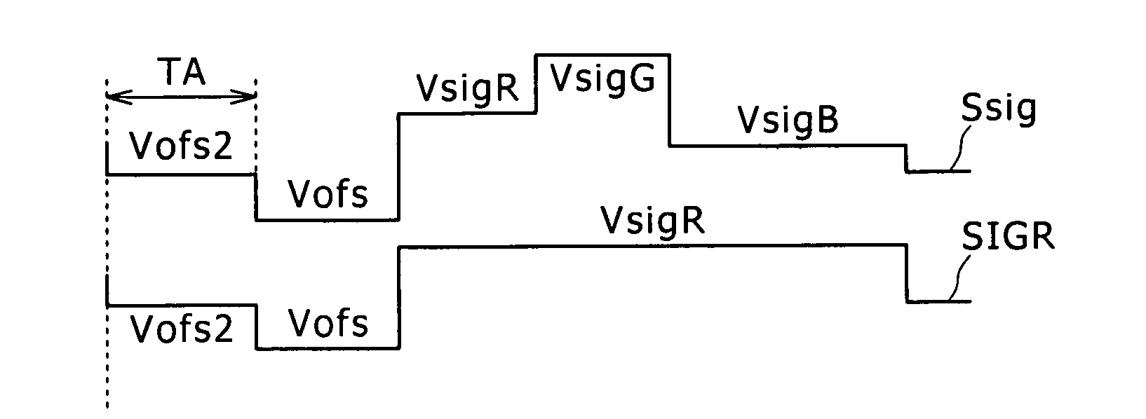
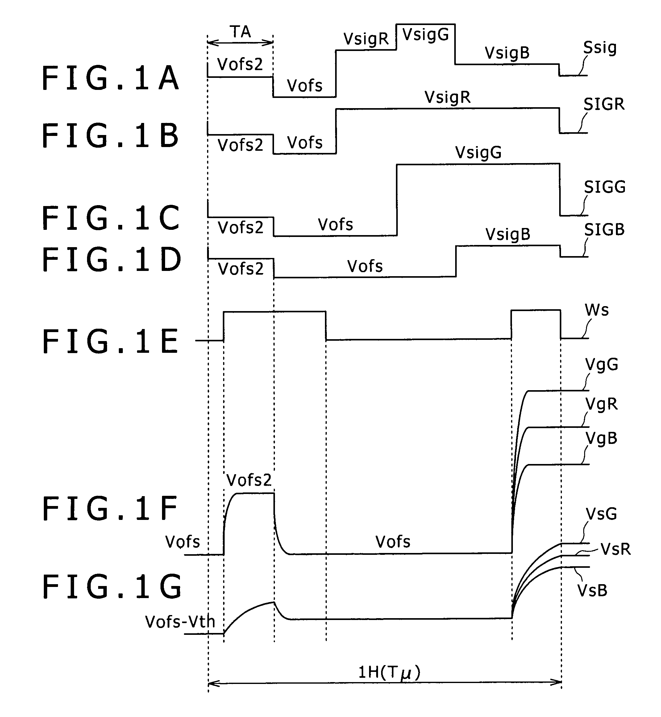
[0073]FIGS. 1A to 1G are time charts illustrating driving timings of pixels in a display apparatus according to a first embodiment of the present invention for comparison with FIGS. 26A to 26G. The display apparatus of the present embodiment has a configuration same as that of the display apparatus described hereinabove with reference to FIG. 24 except that driving of pixels within a no-light emitting period is different. Therefore, in the following description, the configuration of the display apparatus described above is suitably referred to.

[0074]In the operation illustrated in FIGS. 1A to 1G, a driving signal production circuit not shown (refer to FIG. 24) produces one driving signal Ssig common to adjacent pixels 33R, 33G and 33B for red, green and blue which form one pixel of a color image. The driving signal Ssig is outputted to the signal lines SIGR, SIGG and SIGB of the corresponding pixels 33R, 33G and 33B for red, green and blue through t...

second embodiment

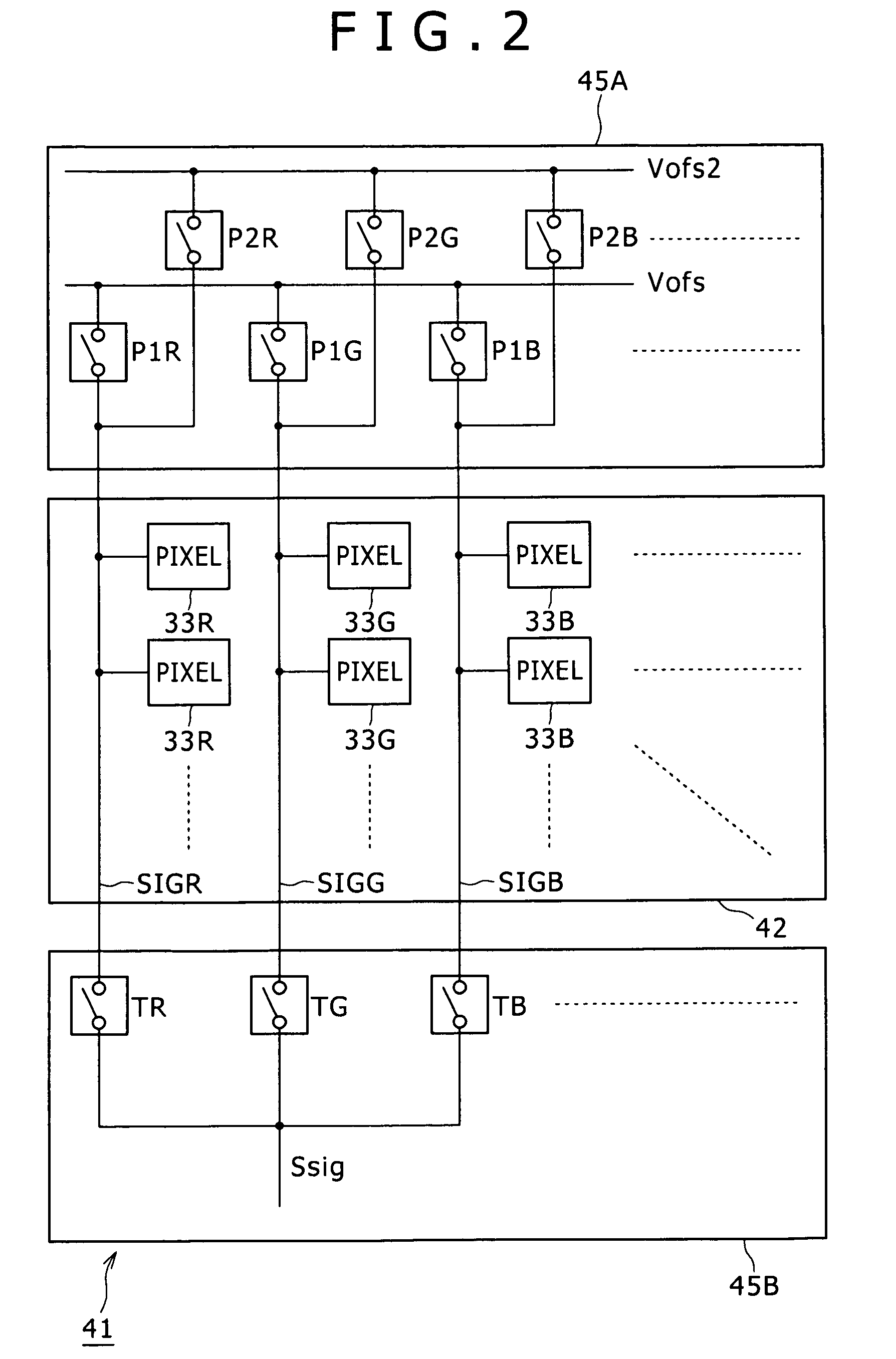
[0095]FIG. 2 shows part of a display apparatus according to a second embodiment of the present invention for comparison with FIG. 24. Referring to FIG. 2, the display apparatus 41 shown is configured such that signal lines SIGR, SIGG and SIGB provided in a display section 42 are driven by horizontal driving circuits 45A and 45B to produce a fixed voltage Vofs and a halftone voltage Vofs2 by a power supply provided in the horizontal driving circuit 45A. Further, as seen from FIGS. 3A and 3B, switch circuits P1R, P1G and P1B and P2R, P2G and P2B are set to an on state to set the signal lines SIGR, SIGG and SIGB to the fixed voltage Vofs and the halftone voltage Vofs2. Further, in the present embodiment, the signal lines SIGR, SIGG and SIGB are set to the fixed voltage Vofs and the halftone voltage Vofs2 by precharge switches. Further, in the present embodiment, the halftone voltage Vofs2 is set as a fixed potential as an example.

[0096]Further, a driving signal Vsig as a time division ...

third embodiment

[0098]It is to be noted that, while, in the embodiments described above, one pixel of a color image is formed from pixels for red, green and blue and signal lines for such pixels for red, green and blue are driven time-divisionally, the present invention is not limited to the embodiments but can be applied widely also where a plurality of signal lines for pixels are driven time-divisionally. Further, the present invention can be applied widely also where only one signal line is driven by a single driving circuit.

[0099]Further, while, in the embodiments described above, an organic EL device is used as a light emitting device, the present invention can be applied widely also where various light emitting devices of the current-driven type are used.

[0100]The present invention can be applied to a display apparatus of the active matrix type by an organic EL device for which, for example, a polycrystalline silicon TFT is used.

[0101]While preferred embodiments of the present invention have ...


PUM


Abstract

The present invention provides a display apparatus, including: a display section including a plurality of pixels disposed in a matrix and a plurality of signal lines and a plurality of scanning lines; and a horizontal driving circuit and a vertical driving circuit configured to drive the signal lines and the scanning lines of the display section to display an image on the display section; each of the pixels including a light emitting device; a signal level storage capacitor, a writing transistor, and a driving transistor.

Description

CROSS REFERENCES TO RELATED APPLICATIONS[0001]The present invention contains subject matter related to Japanese Patent Application JP 2007-236110, filed in the Japan Patent Office on Sep. 12, 2007, the entire contents of which being incorporated herein by reference.BACKGROUND OF THE INVENTION[0002]1. Field of the Invention[0003]This invention relates to a display apparatus and a driving method for a display apparatus and can be applied to a display apparatus of the active matrix type for which, for example, an organic EL (Electro Luminescence) device is used.[0004]2. Description of the Related Art[0005]In related art, various inventions have been proposed for a display apparatus which uses an organic EL device and are disclosed, for example, In U.S. Pat. No. 5,684,365 or Japanese Patent Laid-Open No. Hei 8-234683.[0006]FIG. 4 shows an existing display apparatus of the active matrix type which uses an organic EL device. Referring to FIG. 1, the display apparatus 1 includes a display ...

Claims


Application Information

Patent Timeline
Patent Type & Authority Patents(United States)
IPC IPC(8): G09G3/30
CPCG09G3/3233G09G3/3291G09G2310/0251G09G2310/0297G09G3/3659H01L21/7687H01L29/72H01L2027/11862
Inventor UCHINO, KATSUHIDEYAMAMOTO, TETSURO
Owner JOLED INC
Why Eureka
Try Eureka