Optical touchpad with three-dimensional position determination

a three-dimensional position and optical touch technology, applied in the field of optical touchpad systems, can solve the problems of inability to detect the position of objects in conventional optical touchpad systems, inability to achieve the effect of enhancing control, reducing optical noise, and enhancing frame ra

Inactive Publication Date: 2012-01-10
FLATFROG LAB
View PDF63 Cites 43 Cited by
  • Summary
  • Abstract
  • Description
  • Claims
  • Application Information

AI Technical Summary

Benefits of technology

[0013]This configuration of optical touchpad provides various advantages over known touchpads. For example, the optical touchpad that may be able to provide accurate, reliable information about the position of the object in three-dimensions. The optical touchpad may enable a determination as to whether the object is engaged with the touchpad or hovering just above the touchpad. When the object is in contact with the optical touchpad, the optical touchpad may enable a determination of the force applied by the object to the optical touchpad. The optical touchpad may enable a determination of an object type of the object. These and other determinations of information related to the object may enhance the control provided by the touchpad system to the user as an electronic interface. The operation of the optical touchpad may further enable an enhanced frame rate, reduced optical noise in the optical signal(s) guided to the one or more sensors, augment the ruggedness of the optical touchpad, an enhanced form factor (e.g., thinner), and / or provide other advantages.

Problems solved by technology

However, conventional optical touchpad systems may include various drawbacks.
For example, conventional optical touchpad systems may be costly, imprecise, bulky, temperamental, fragile, energy inefficient, or may have other weaknesses and / or drawbacks.
Further, conventional systems may only be able to detect position of an object (e.g., a fingertip, a palm, a stylus, etc.) when the object is engaged with the touchpad.
This may limit the position-detection of optical touchpad systems to detecting the position of the object in the plane of the surface of the touchpad.
This may increase the bulk of the touchpad, decrease a ruggedness of the touchpad, decrease an efficiency of the touchpad, limit the applications for which the touchpad is feasible, and / or include other drawbacks and / or limitations.
These and other limitations of conventional touchpad systems may restrict the types of applications for which touchpad systems may be employed as human / machine interfaces.
Various other drawbacks exist with known touchpads, including optical touchpads.

Method used


Image

  • Optical touchpad with three-dimensional position determination
  • Optical touchpad with three-dimensional position determination
  • Optical touchpad with three-dimensional position determination

Examples


Embodiment Construction

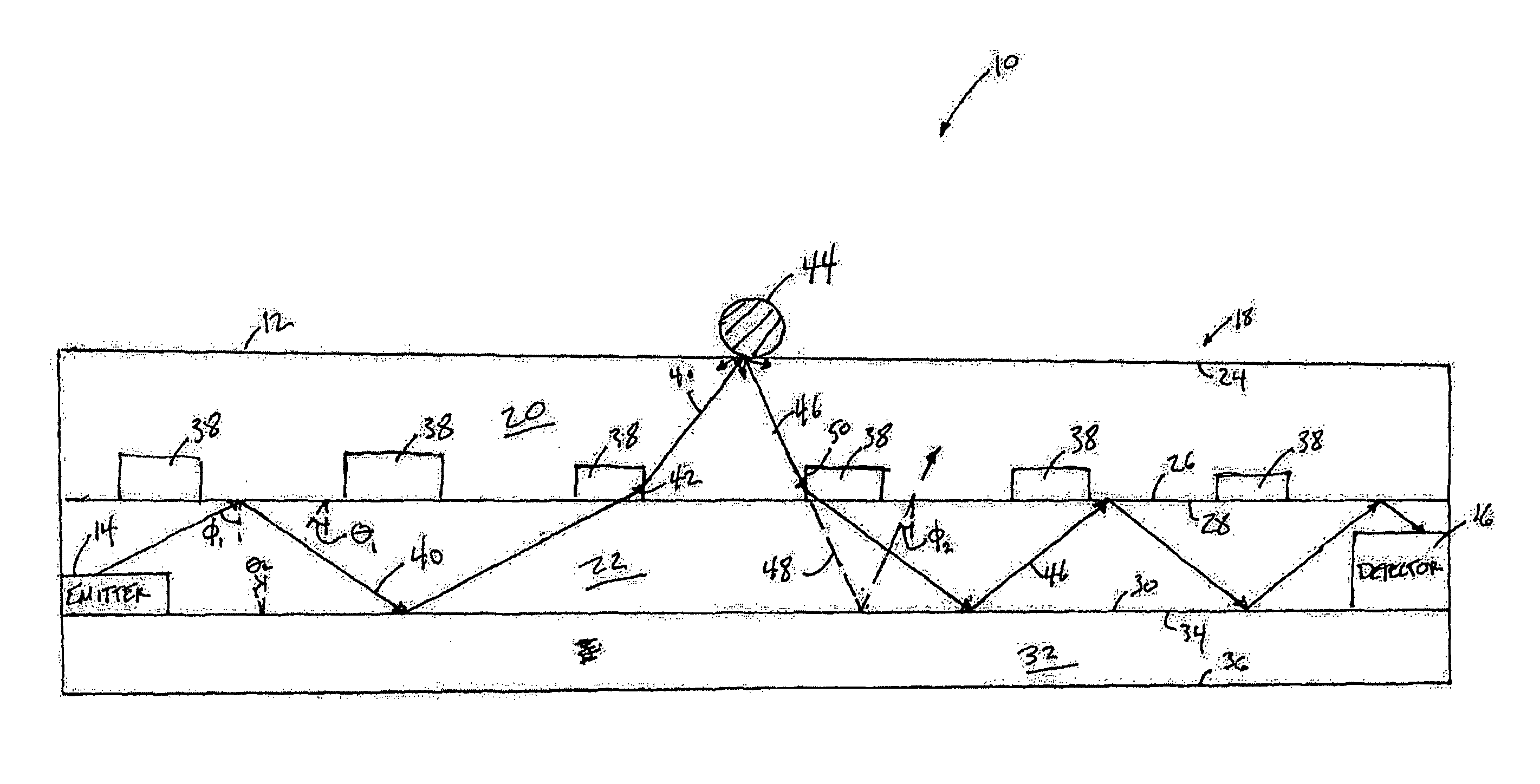
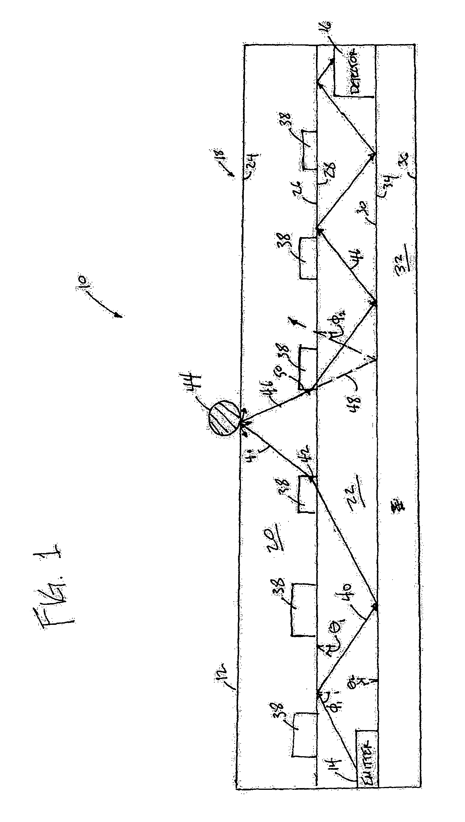
[0021]FIG. 1 illustrates an optical touchpad system 10 according to one or more embodiments of the invention. Optical touchpad system 10 may include an interface surface 12, one or more emitters 14, one or more detectors 16, and a waveguide 18. Interface surface 12 is configured such that a user can engage interface surface 12 with an object (e.g., a fingertip, a stylus, etc.). Optical touchpad system 10 detects information related to a position of the object with respect to the interface surface 12 (e.g., a distance between the object and interface surface 12, a position of the object in a plane generally parallel with the plane of interface surface 12, etc.).

[0022]Emitters 14 emit electromagnetic radiation, and may be optically coupled with waveguide 18 so that electromagnetic radiation emitted by emitters 14 may be directed into waveguide 18. Emitters 14 may include one or more Organic Light Emitting Devices (“OLEDs”), lasers (e.g., diode lasers or other laser sources), LED, HCFL...


PUM


Abstract

An optical touchpad that may be able to provide accurate, reliable information about the position of an object in three-dimensions. The optical touchpad may enable a determination as to whether the object is engaged with the touchpad or hovering just above the touchpad. When the object is in contact with the optical touchpad, the optical touchpad may enable a determination of the force applied by the object to the optical touchpad. The optical touchpad may enable a determination of an object type of the object. These and other determinations of information related to the object may enhance the control provided by the touchpad system to the user as an electronic interface. The operation of the optical touchpad may further enable an enhanced frame rate, reduced optical noise in the optical signal(s) guided to the one or more sensors, augment the ruggedness of the optical touchpad, an enhanced form factor (e.g., thinner), and / or provide other advantages.

Description

FIELD OF THE INVENTION[0001]The invention relates to an optical touchpad system, with a multilayer waveguide that includes at least one total internal reflection mirror, for determining information relating to a position of an object with respect to an interface surface of the optical touchpad system, including three-dimensional position information and / or contact information.BACKGROUND OF THE INVENTION[0002]Generally, touchpad systems are implemented for a variety of applications. Some of these applications include, computer interfaces, keypads, keyboards, and other applications. Various types of touch pads are known. Optical touch pads have certain advantages over some other types of touch pads at least for some applications. Various types of optical touchpad systems may be used in some or all of these applications. However, conventional optical touchpad systems may include various drawbacks.[0003]For example, conventional optical touchpad systems may be costly, imprecise, bulky, ...

Claims


Application Information

Patent Timeline
Patent Type & Authority Patents(United States)
IPC IPC(8): G06F3/042G06K11/06G08C21/00G06F3/041
CPCG06F3/0346G06F3/0425G06F3/0428G06F2203/04109
Inventor ELIASSON, JONAS OVE PHILIPLARSEN, NIELS AGERSNAPBASTUE, JENSOSTERGAARD, JENS WAGENBLAST STUBBE
Owner FLATFROG LAB
Why Eureka
Try Eureka