Inverse horn loudspeakers

a loudspeaker and inverse horn technology, applied in the direction of transducer details, instruments, electrical transducers, etc., can solve the problems of low efficiency, cost and flexibility of use, large speakers typically being less efficient, and less flexible in placement in the listener's home, so as to achieve low frequency response and high efficiency

Inactive Publication Date: 2012-01-10
CLEMENTS PHILIP R
View PDF24 Cites 7 Cited by
  • Summary
  • Abstract
  • Description
  • Claims
  • Application Information

AI Technical Summary

Benefits of technology

[0009]Embodiments of the present invention provide loudspeakers with extended, even, low frequency response having high efficiency, using moderate and smaller enclosures and transducers.
[0010]In one embodiment, a loudspeaker enclosure has several compression chambers, including a primary compression chamber, and one or more secondary compression chambers. A transducer, such as a woofer, is mounted in a wall of the enclosure, radiating the acoustic output from its front side into the external environment and from its back side into the primary compression chamber. The primary compression chamber and the plurality of secondary compression chambers form an inverse horn, exiting from the primary compression chamber and by way of a series of compression steps couple the acoustic output to an exit to the external environment. The compression chambers each act to either increase or maintain the acoustic pressure from the prior compression chamber, thereby loading the driver for reduced and controlled diaphragm motions while efficiently coupling the transducer output to the environment. Further, a resonance-distortion filter chamber within the enclosure is acoustically coupled into one of the compression chambers. The filter chamber reduces parasitic pipe resonances and / or distortion components that arise from the output of the series of compression chambers. The filter chamber also couples its internal volume to the total internal volume of the system at low frequencies, thereby increasing the effective total enclosure volume, and thus lowering system resonance which allows for lower bass frequency extension, and thereby improving efficiency and low frequency extension.

Problems solved by technology

These two goals are often in opposition, and it is well known that obtaining extended low frequency response typically requires large, floor standing speakers with significant internal volumes, and / or large diameter woofers.
Both options require tradeoffs in terms of efficiency, cost and flexibility of use, with large speakers typically being less efficient, costing more, and being less flexible in terms of placement in a listener's home.
The basic sealed enclosure or ‘acoustic suspension’ system, while the simplest of the devices, has significant limitations, typically including low efficiency and requiring very large driver diaphragm area and excursion capability to achieve reasonable outputs at low frequencies.
These improvements are offset by problems with enclosure standing wave and pipe resonances exiting the vent, and for standard, maximally flat alignments, the systems are substantially ineffective at extending response below the free-air resonance of the transducer. in addition, vented design have problems with extreme diaphragm excursions below the cut-off frequency, reducing maximum output or requiring high pass filters to protect the woofer.
In addition, the transmission lines utilize substantial damping material throughout the line length, which further reduces efficiency.
Again, this requirement results in very large sizes for a given low frequency capability.
These systems also suffer in having uneven frequency response and poor group delay, due to uncontrolled resonances in the transmission line.

Method used


Image

  • Inverse horn loudspeakers
  • Inverse horn loudspeakers
  • Inverse horn loudspeakers

Examples


Embodiment Construction

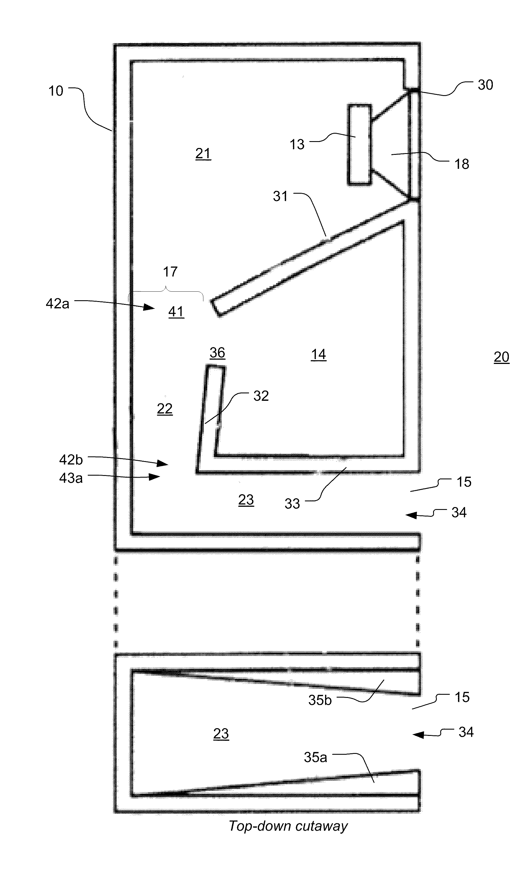
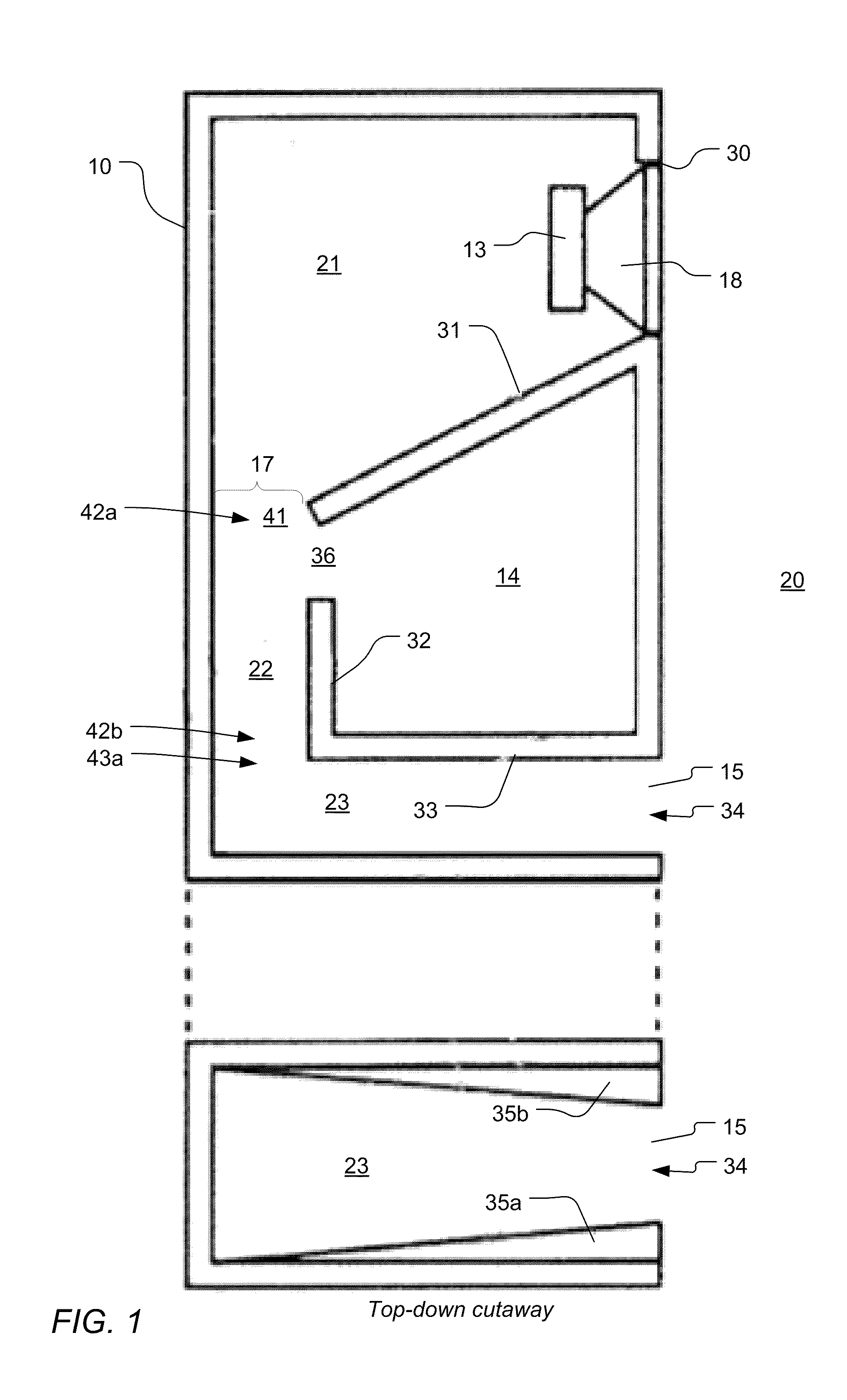
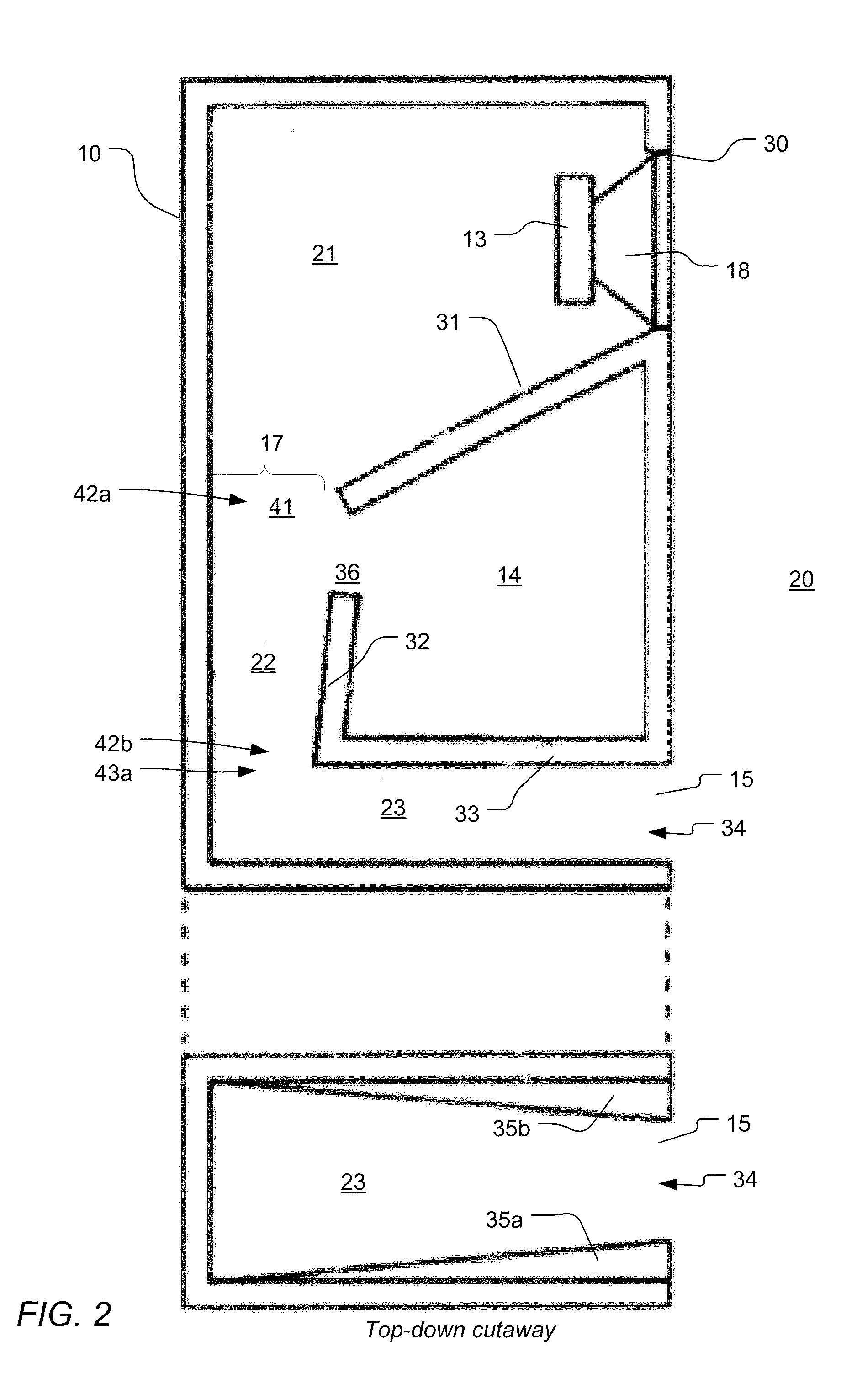
[0034]FIG. 1 shows an embodiment of the invention with inverse horn enclosure system 10 comprising at least one electro-acoustic transducer 13 with a movable diaphragm 18 for converting an electrical input signal into a corresponding acoustic output at a pressure. The transducer 13 is mounted in a transducer opening 30 and radiates acoustic output from its front side to an external environment 20, and radiates from acoustic output from its backside into a first (primary) compression chamber 21 within the enclosure 10.

[0035]Compression chamber 21 is at least partially bounded by horn plate 31, which is configured to compress the acoustic output, and thus increase the pressure of the acoustic output, from diaphragm 18 towards an exit 41 of the chamber 21. The compressed acoustic output continues through entrance 42a of a secondary compression chamber 22 at least partially bounded by horn plate 32, through to the exit 42b of compression chamber 22. In this embodiment, compression chamb...


PUM


Abstract

In a low frequency transducer system a multi-compression chamber, inverse horn structure is employed in combination with a resonance-distortion filter chamber. The filter chamber effectively expands the effective enclosure volume at low frequencies and connected to one of the compression chambers filter parasitic resonances and distortion and allowing the system to more efficiently reproduce low frequencies while being able to use smaller diameter transducers and maintaining good system sensitivity. Compression chambers are organized for constant or continuous compression on a section-by-section basis throughout the inverse horn system.

Description

CROSS REFERENCE TO RELATED APPLICATIONS[0001]This application claims the benefit under 35 U.S.C. his application claims the benefit under 35 U.S.C. §119(e) of provisional application Ser. No. 61 / 240,589 filed on Sep. 8, 2009, which is incorporated by reference herein.FIELD OF THE INVENTION[0002]The present invention relates to loudspeaker enclosure systems, and more particularly, to low frequency enclosure systems.BACKGROUND OF THE INVENTION AND RELATED ART[0003]In the art of loudspeaker systems it is desirable to obtain the extended low frequency response. In addition, it is generally desirable to minimize the size of the loudspeaker enclosure, for example to reduce cost and allow for more flexible placement. These two goals are often in opposition, and it is well known that obtaining extended low frequency response typically requires large, floor standing speakers with significant internal volumes, and / or large diameter woofers. Both options require tradeoffs in terms of efficienc...

Claims


Application Information

Patent Timeline
Patent Type & Authority Patents(United States)
IPC IPC(8): H04R1/20G10K11/00
CPCH04R1/2888H04R1/02H04R2440/03H04R1/2857H04R1/2865H04R1/345H04R1/2861
Inventor CLEMENTS, PHILIP R.
Owner CLEMENTS PHILIP R
Why Eureka
Try Eureka