Snap-in wire tie
a technology of snap-in wire ties and snap-in anchors, which is applied in the direction of walls, building components, protective buildings/shelters, etc., can solve the problems of providing a completely reinforced arrangement of both inner and outer, and lack of a simplified snap-in anchor to encapture reinforcement, etc., and achieves low unit cost and economics of manufacture.
- Summary
- Abstract
- Description
- Claims
- Application Information
AI Technical Summary
Benefits of technology
Problems solved by technology
Method used
Image
Examples
first embodiment
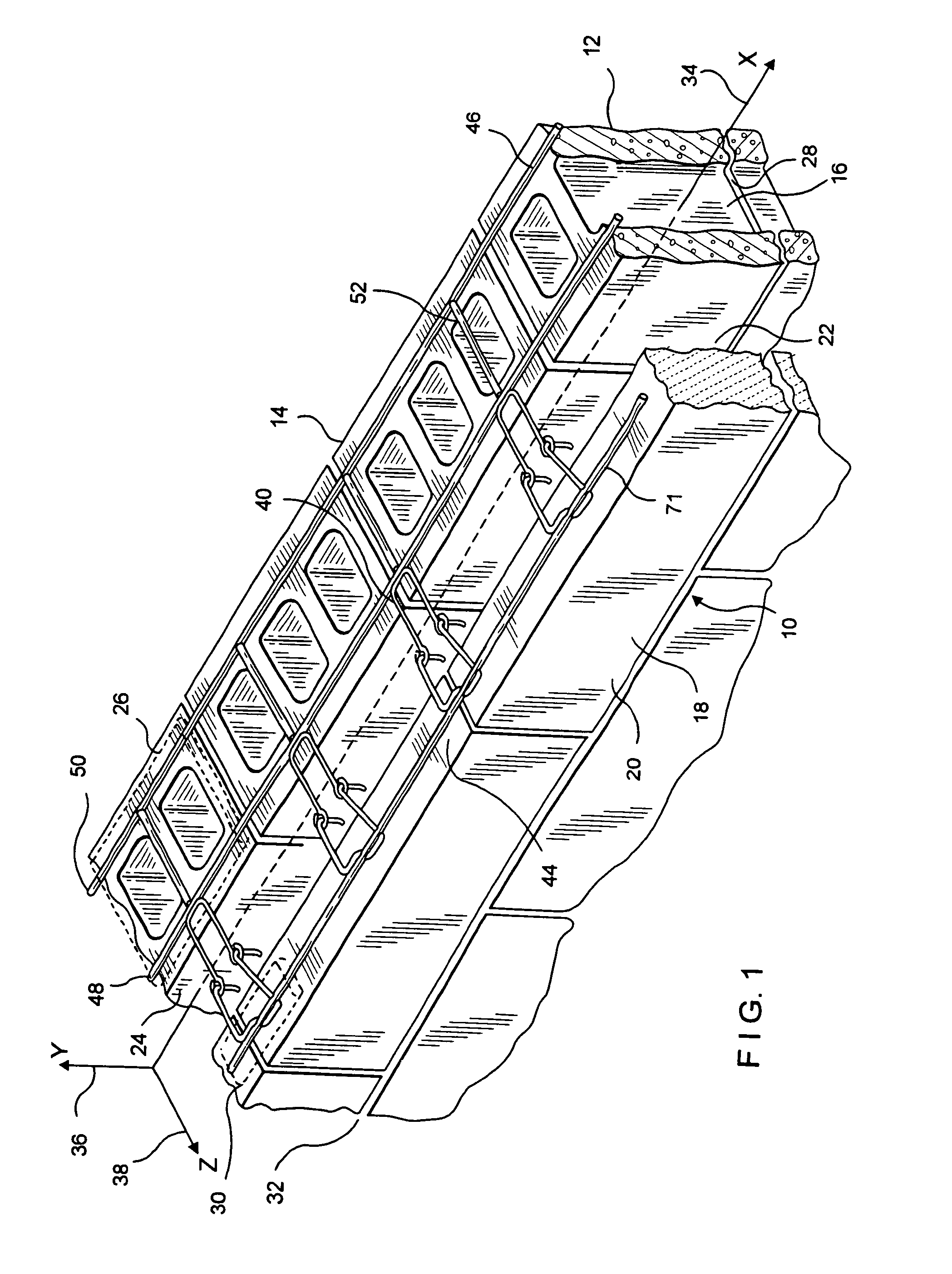
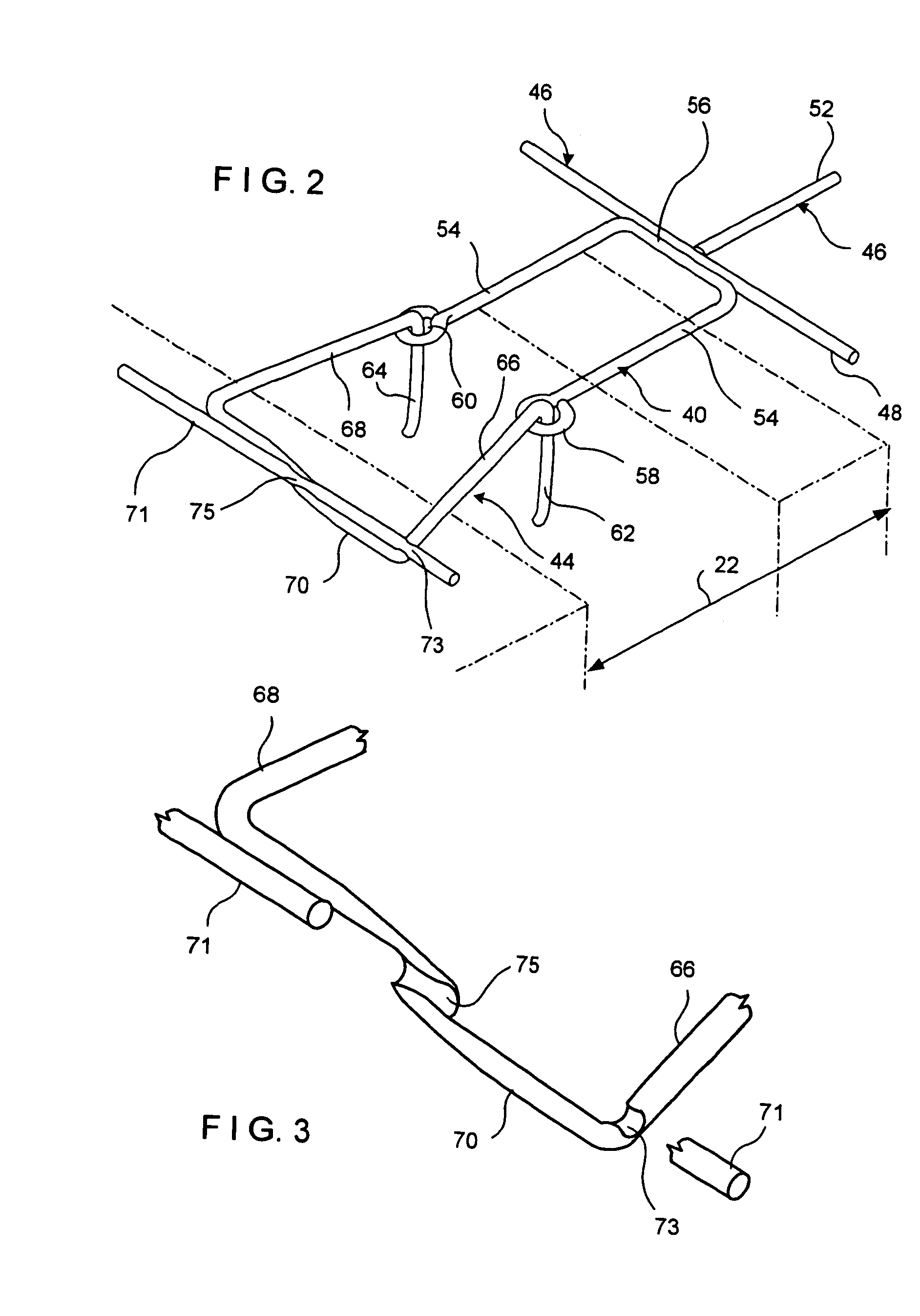
[0046]The description which follows is of three embodiments of the snap-in wire tie devices of this invention, which devices are suitable for cavity wall seismic applications. Two of the embodiments apply to cavity walls with masonry block inner wythes, and the third, to cavity walls with dry wall (sheetrock) inner wythes. The wall anchor of the first embodiment is adapted from that shown in U.S. Pat. No. 6,789,365 of the inventors hereof.
[0047]Referring now to FIGS. 1 and 3, the first embodiment of the snap-in wire tie system including a seismic wire reinforcement of this invention is shown and is referred to generally by the numeral 10. In this embodiment, a wall structure 12 is shown having a backup wall 14 of masonry blocks 16 and a facing wall or veneer 218 of facing brick or stone 20. Between the backup wall 14 and the facing wall 18, a cavity 22 is formed, which cavity 22 extends outwardly from surface 24 of backup wall 14.
[0048]In this embodiment, successive bed joints 26 an...
second embodiment
[0063]In the second embodiment in adapting the snap-in wire tie for high-span applications, it is noted that the above-described arrangement of wire formatives is strengthened in several respects. First, in place of the standard 9-gage (0.148-inch diameter) wall reinforcement wire, a 3 / 16-inch (0.187-inch diameter) wire is used. Additionally a 0.250-inch wire is used to form both the wall anchor 140 and the veneer anchor 144. Here the insertion ends of only the wall anchor 140 and the snap-in wire tie 144 are compressively reduced in height. In this regard, wall anchor 140 is reduced by up to 70%, but at least by the amount required to be within the envelope of wall reinforcement 146. Thus, upon butt welding the height is not increased.
[0064]Also, the successive insulation strips 123 when in an abutting relationship the one with the other are sufficiently resilient to seal at seam 125 without air leakage therebetween. The extended insulation-spanning portions 142 of wall anchor 140 ...
third embodiment
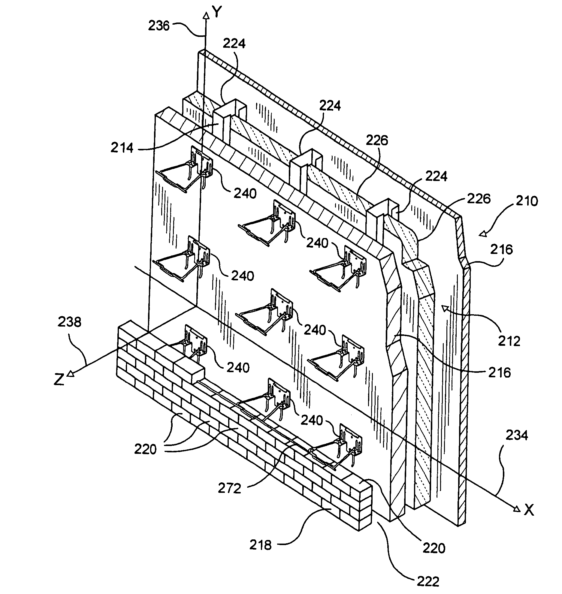
[0068]Referring now to FIGS. 6 to 8, the snap-in wire tie system is shown and is referred to generally by the numeral 210. The system 210 employs a sheetmetal wall anchor, Catalog #HB-200. The dry wall structure 212 is shown having an interior or inner wythe 214 with a wallboard 216 as the interior and exterior facings thereof. An exterior or outer wythe 218 of facing brick 220 is attached to dry wall structure 212 and a cavity 222 is formed therebetween. The dry wall structure 212 is constructed to include, besides the wallboard facings 16, vertical channels 224 with insulation layers 226 disposed between adjacent channel members 224. Selected bed joints 228 and 230 are constructed to be in cooperative functional relationship with the snap-in wire tie described in more detail below. For purposes of discussion, the exterior surface 232 of the interior wythe 214 contains a horizontal line or x-axis 234 and an intersecting vertical line or y-axis 236. A horizontal line or z-axis 238 a...
PUM
 Abstract
Description
Claims
Application Information
 - R&D
- Intellectual Property
- Life Sciences
- Materials
- Tech Scout
- Unparalleled Data Quality
- Higher Quality Content
- 60% Fewer Hallucinations
Browse by: Latest US Patents, China's latest patents, Technical Efficacy Thesaurus, Application Domain, Technology Topic, Popular Technical Reports.
© 2025 PatSnap. All rights reserved.Legal|Privacy policy|Modern Slavery Act Transparency Statement|Sitemap|About US| Contact US: help@patsnap.com


