Snap-in wire tie

a technology of snap-in wire ties and snap-in anchors, which is applied in the direction of shock-proofing, building components, structural elements, etc., can solve the problems of providing a completely reinforced arrangement of both the inner and outer, and lack of a simplified snap-in anchor to encapture the reinforcement, etc., and achieves low unit cost and economics of manufacture.

Active Publication Date: 2008-02-05
HOHMANN & BARNARD INC
View PDF38 Cites 84 Cited by
  • Summary
  • Abstract
  • Description
  • Claims
  • Application Information

AI Technical Summary

Benefits of technology

[0042]It is a further object of the present invention to provide a snap-in wire tie construction system comprising a limited number of component parts that are economical of manufacture resulting in a relatively low unit cost.
[

Problems solved by technology

Besides earthquake protection, the failure of several high-rise buildings to withstand wind and other lateral forces has resulted in the incorporation of a requirement for continuous wire reinforcement in the Uniform Building Cod

Method used


Image

  • Snap-in wire tie
  • Snap-in wire tie
  • Snap-in wire tie

Examples


first embodiment

[0056]The description which follows is of three embodiments of the snap-in wire tie devices of this invention, which devices are suitable for cavity wall seismic applications. Two of the embodiments apply to cavity walls with masonry block inner wythes, and the third, to cavity walls with a dry wall (sheetrock) inner wythes. The wall anchor of the first embodiment is adapted from that shown in U.S. Pat. No. 6,789,365 of the inventors hereof.

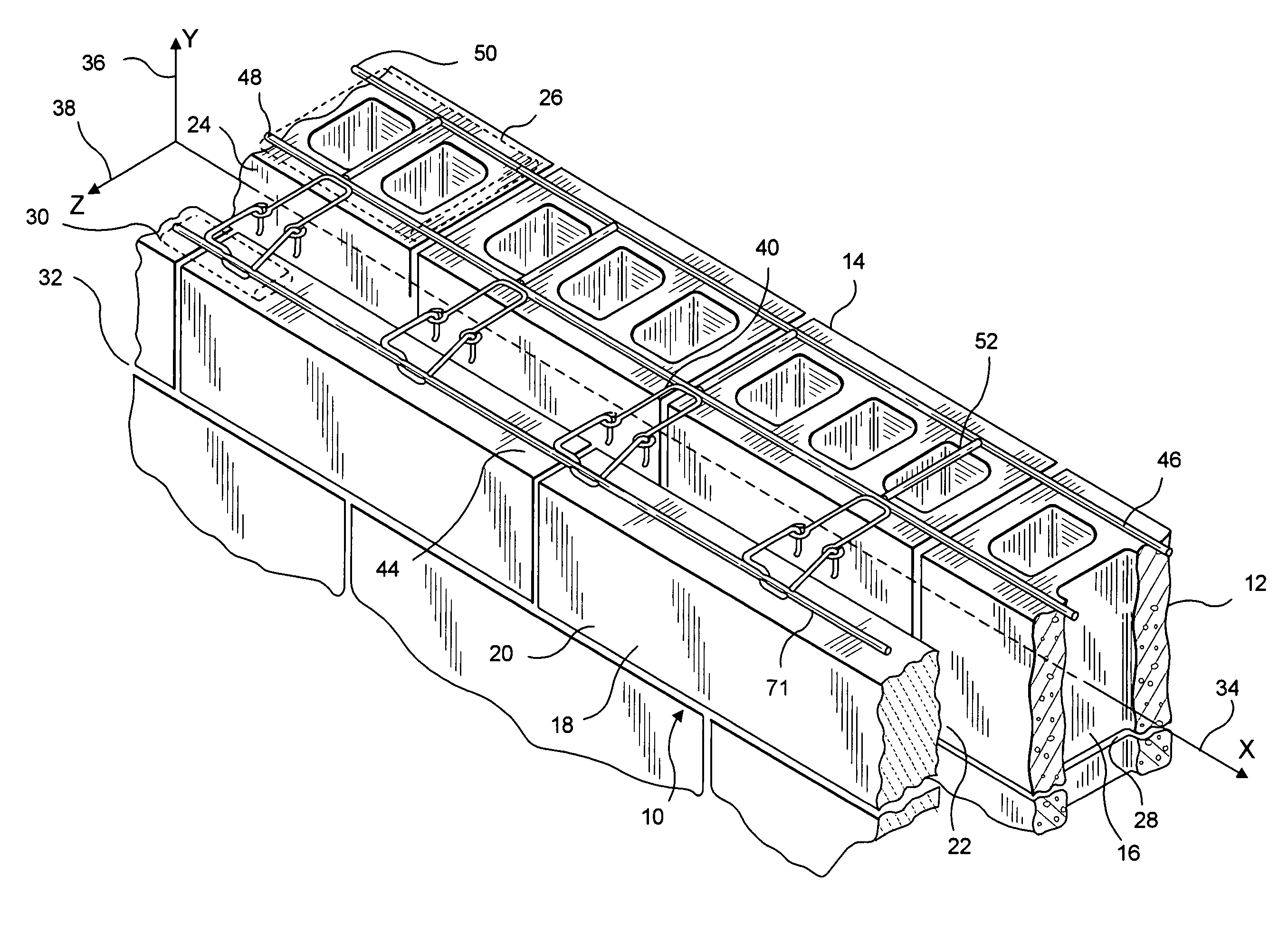
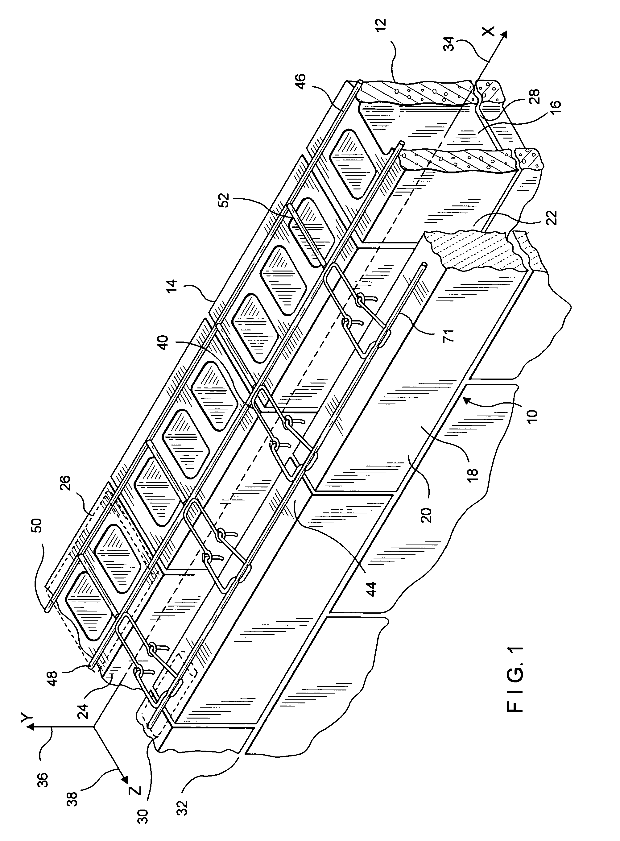
[0057]Referring now to FIGS. 1 and 3, the first embodiment of the snap-in wire tie system including a seismic wire reinforcement of this invention is shown and is referred to generally by the numeral 10. In this embodiment, a wall structure 12 is shown having an backup wall 14 of masonry blocks 16 and a facing wall or veneer 218 of facing brick or stone 20. Between the backup wall 14 and the facing wall 18, a cavity 22 is formed, which cavity 22 extends outwardly from surface 24 of backup wall 14.

[0058]In this embodiment, successive bed joints 26...

second embodiment

[0073]In the second embodiment in adapting the snap-in wire tie for high-span applications, it is noted that the above-described arrangement of wire formatives is strengthened in several respects. First, in place of the standard 9-gage (0.148-inch diameter) wall reinforcement wire, a 3 / 16-inch (0.187-inch diameter) wire is used. Additionally a 0.250-inch wire is used to form both the wall anchor 140 and the veneer anchor 144. Here the insertion ends of only the wall anchor 140 and the snap-in wire tie 144 are compressively reduced in height as described in Hohmann, U.S. Pat. No. 6,668,505. In this regard, wall anchor 140 is reduced by up to 70%, but at least by the amount required to be within the envelope of wall reinforcement 146. Thus, upon butt welding the height is not increased.

[0074]Also, the successive insulation strips 123 when in an abutting relationship the one with the other are sufficiently resilient to seal at seam 125 without air leakage therebetween. The extended ins...

third embodiment

[0078]Referring now to FIGS. 6 to 8, the snap-in wire tie system is shown and is referred to generally by the numeral 210. The system 210 employs a sheetmetal wall anchor, Catalog #HB-200. The dry wall structure 212 is shown having an interior wythe 214 with a wallboard 216 as the interior and exterior facings thereof. An exterior wythe 218 of facing brick 220 is attached to dry wall structure 212 and a cavity 222 is formed therebetween. The dry wall structure 212 is constructed to include, besides the wallboard facings 216, vertical channels 224 with insulation layers 226 disposed between adjacent channel members 224. Selected bed joints 228 and 230 are constructed to be in cooperative functional relationship with the snap-in wire tie described in more detail below. For purposes of discussion, the exterior surface 232 of the interior wythe 214 contains a horizontal line or x-axis 234 and an intersecting vertical line or y-axis 236. A horizontal line or z-axis 238 also passes throug...


PUM


Abstract

A seismic construction system for a cavity wall is disclosed. The system is shown in three exemplary applications—a masonry backup wall with ladder- or truss-type reinforcement cooperating with a snap-in wire tie; a masonry backup wall with ladder- or truss-type reinforcement with a high-span wall anchor cooperating with a low-profile, snap-in wire tie; and a drywall backup wall with internal insulation, a sheetmetal wall anchor, and snap-in wire ties. The snap-in wire ties accommodate a continuous reinforcing wire for the outer wythe, which reinforcing wire snaps into the wire housings therefor with a predetermined force. With the interconnected wall and veneer anchors and the respective reinforcing elements a seismic construct is formed.

Description

BACKGROUND OF THE INVENTION[0001]1. Field of the Invention[0002]This invention relates to an improved anchoring arrangement for use in conjunction with a seismic construction system for cavity walls having an inner wythe and an outer wythe. More particularly, the invention relates to construction accessory devices, namely, snap-in wire ties, for emplacement in the outer wythe. These devices accommodate the encapturing of a reinforcing wire therewithin. The invention is applicable to seismic structures having an outer wythe of brick or stone facing in combination with an inner wythe of masonry block or dry wall construction and with various forms of insulation.[0003]2. Description of the Prior Art[0004]In the past, investigations relating to the effects of various forces, particularly lateral forces, upon brick veneer masonry construction demonstrated the advantages of having a continuous wire embedded in the mortar joint of anchored veneer walls, such as facing brick or stone veneer...

Claims


Application Information

Patent Timeline
IPC IPC(8): E04B1/38E04B1/16E04B1/98E04B5/00E04C1/40E04C5/00E04H9/02
CPCE04B1/4178E04B1/4185E04H9/02E04H9/021
Inventor HOHMANN, JR., RONALD P.HOHMANN, RONALD P.
Owner HOHMANN & BARNARD INC
Why Eureka
Try Eureka