Endocardial lead removing apparatus

a technology of endocardial leads and endocardial leads, which is applied in the field of endocardial lead removal apparatus, can solve the problems of increasing electrode resistance, and unable to remove endocardial leads in the heart and venous path,

Active Publication Date: 2012-01-17
SPECTRANETICS
View PDF29 Cites 293 Cited by
  • Summary
  • Abstract
  • Description
  • Claims
  • Application Information

AI Technical Summary

Problems solved by technology

Although the state of the art in implemented pulse generator or pacemaker technology and endocardial lead technology has advanced considerably, endocardial leads nevertheless occasionally fail, due to a variety of reasons, including breakage of a lead, insulation breaks, breakage of the inner helical coil conductor and an increase in electrode resistance.
Although it obviously would be desirable to easily remove such unused leads, in the past surgeons usually have avoided attempts to remove inoperative leads because the risk of removing them exceeded the risk of leaving them in.
The risks of leaving unused myocardial leads in the heart and venous path include increased likelihood that an old lead may facilitate infection, which in turn may necessitate removal of the lead to prevent continued bacteremia and abcess formation.
Furthermore, there is an increased likelihood of the formation of blood clots in the atrial chamber about entangled leads.
Such clots may embolize to the lung and produce severe complications and even fatality.
Furthermore, the presence of unused leads in the venous pathway and inside the heart can cause considerable difficulty in the positioning and attachment of new endocardial leads in or to the heart.
Even then, it is possible that a clot has formed so the removal of the leads causes various sized emboli to pass to the lungs, producing severe complications.
In cases where the lead tip has become attached by scar tissue to the myocardial wall, removal of the lead always has presented problems and risks.
Sufficient traction on such leads in a removal attempt could cause disruption of the myocardial wall prior to release of the embedded lead tip.
The tines or flanges of other types of leads that are not tightly scarred to the myocardial wall present similar risks.
Continual strong pulling or twisting of the outer free end of the lead could cause rupture of the atrial wall or the ventricular wall if there is such tight circumferential encasement of adherent channel scar tissue in the venous path.
The risks of removing the lead by such traction and rotation of the lead may be high enough so that, if it becomes imperative that the lead be removed (as in the case of infection), many surgeons have elected to open the patient's chest and surgically remove the lead rather than attempt removal by applying traction and rotation thereto.

Method used


Image

  • Endocardial lead removing apparatus
  • Endocardial lead removing apparatus
  • Endocardial lead removing apparatus

Examples


first embodiment

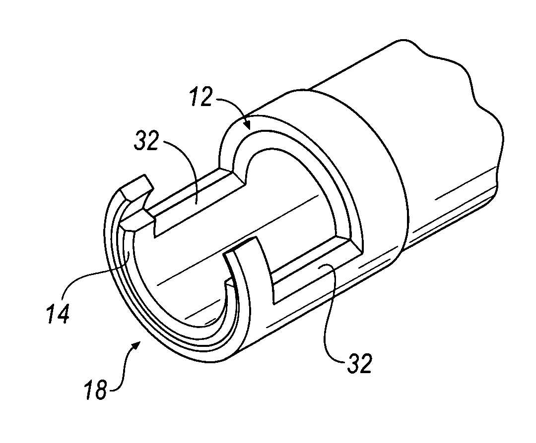
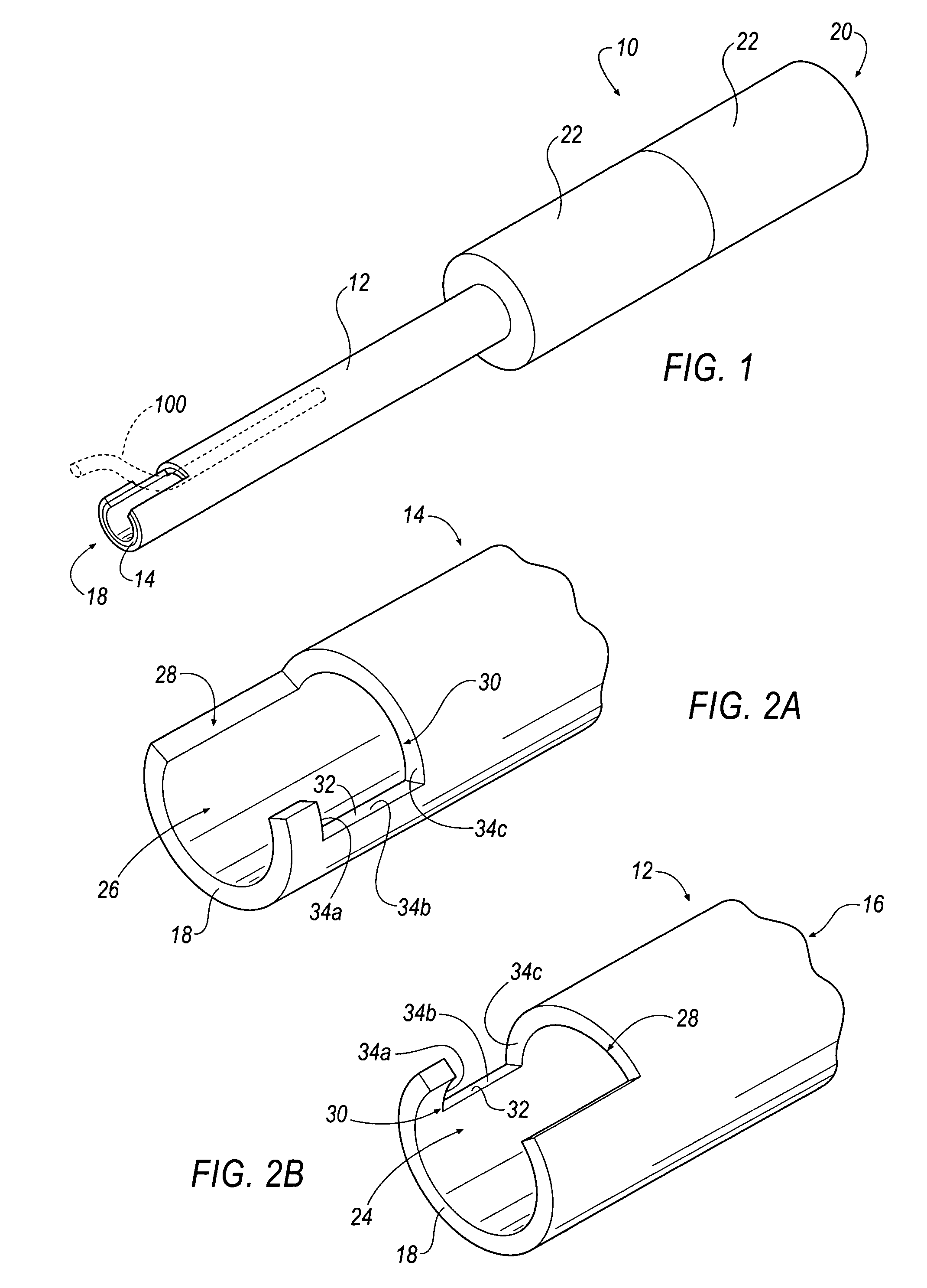
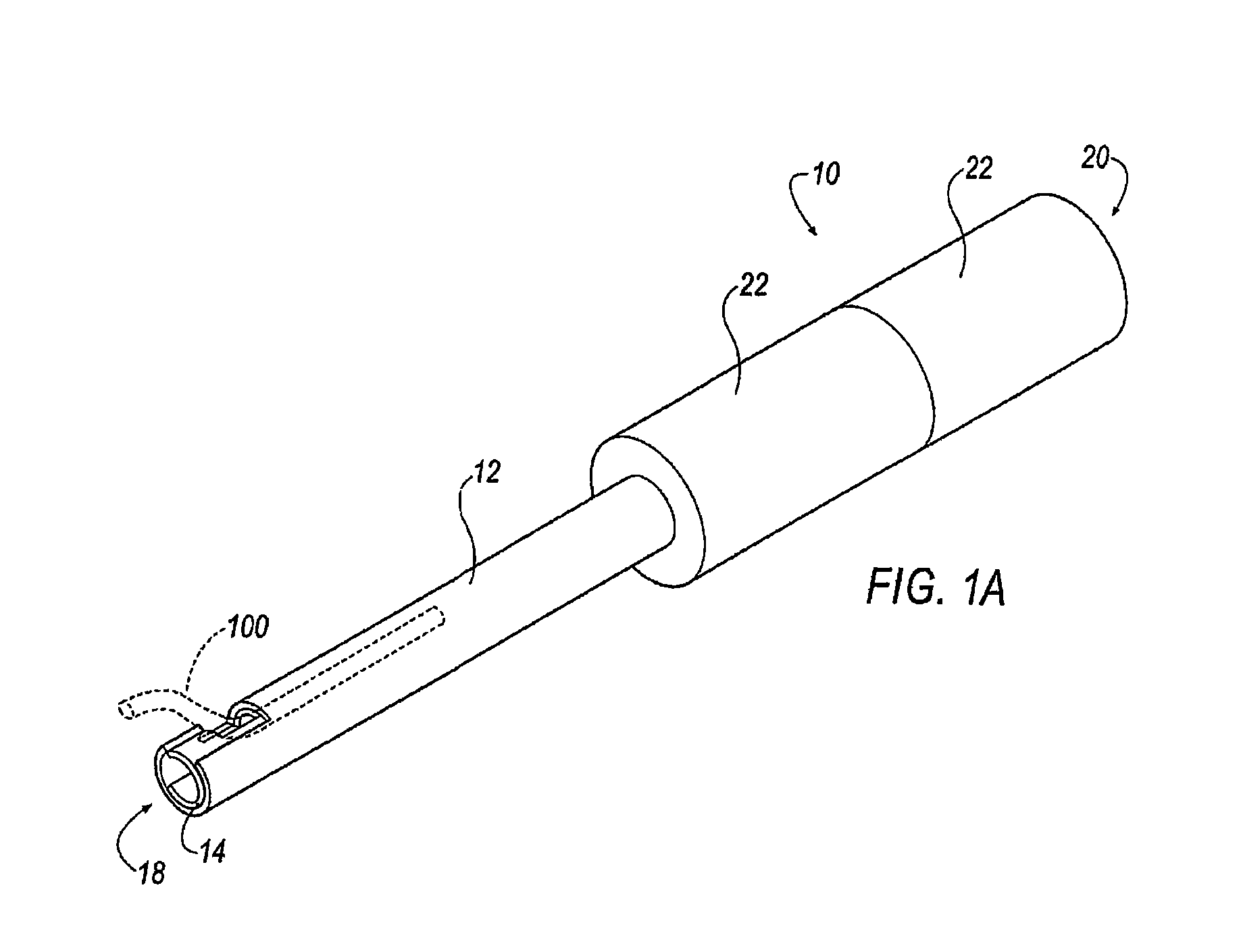
[0034]In operation, apparatus 10 of FIGS. 1-3 is inserted within a patient's chest cavity, blood vessel, or other anatomical part containing a lead (not shown) and receives a lead 100 (shown in phantom in FIG. 1) within the inner cavity 16 of the inner tubular member 14. Once the distal ends 18 of the apparatus 10 are positioned as near as possible to the embedded electrode (not shown) within the patient's body the lead 100 is received within the channels 24, 26. Each of the tubular members 12, 14 are independently rotatable and when rotated in opposite directions the lead 100 is captured in a completely enclosed window formed between the cutting surfaces 32 of each channel 24, 26 as shown in FIG. 1A. Additional torque applied to the handles 22 and further rotation of the members 12, 14 cuts through the lead 100. The severed portion of the lead 100 remains within the inner cavity 16 of the inner tubular member 14 and the apparatus 10 is removed from the patient's body.

[0035]Another ...

fifth embodiment

[0052]Referring to FIGS. 11-12, the apparatus 10 of the present invention is illustrated. The apparatus 10 includes a tubular member 512 defining a tubular wall 560 and a longitudinal axis A-A. The tubular member 512 is generally flexible and made from a plastic or polymer material; however, any material is contemplated by the present invention. The tubular member 512 and tubular wall 560 define an inner cavity 516. The inner cavity 516 is generally offset from the longitudinal axis A-A of the tubular member 512 in order to accommodate a blade 552 and adjustment mechanism 546 within the tubular wall 560.

[0053]The apparatus 10 includes the blade 552 disposed within the tubular wall 560 of the tubular member 512. The blade 552, by way of the adjustment mechanism 546, is moveable between a retracted position and an extended position. Further, the blade 552 includes a generally arcuate cutting surface 532.

[0054]The adjustment mechanism 546 of the fifth embodiment is pneumatically actuat...


PUM


Abstract

The invention provides an apparatus having a tubular member for receiving an endocardial lead implanted within a patient's body. Disposed generally at a distal end of the tubular member is at least one blade or cutting surface. An adjustment mechanism moves the blade between retracted and extended positions to engage the cutting surface with the endocardial lead to cut the lead. Once severed, the cut portion of the lead remains within an inner channel of the tubular member and the apparatus and cut portion of the lead are removed from within the patient. Various embodiments include the blade pivotally connected to the distal end of the tubular member and activated by a wire adjustment mechanism. Others include a metallic wire for slicing through the lead. Still others include a pneumatically actuated adjustment mechanism that inflates to move the blade and engage the cutting surface with the lead.

Description

FIELD OF THE INVENTION[0001]This invention relates generally to an endocardial lead removing apparatus and, more particularly, to an apparatus that cuts the endocardial lead and, in some embodiments, captures the cut portion to remove the lead from the patient's body.BACKGROUND OF THE INVENTION[0002]In the past, various types of endocardial leads and electrodes have been introduced into different chambers of a patient's heart, including among other locations, the right ventricle, right atrial appendage, and atrium, as well as the coronary sinus. These flexible leads are often composed of an insulator sleeve that contains an implanted helical coil conductor that is attached to an electrode tip. This electrode is placed in contact with myocardial tissue by passage through a venous access, often the subclavian vein or one of its tributaries, which leads to the endocardial surface of the heart chambers. The tip with the electrode contact is held in place by trabeculations of myocardial ...

Claims


Application Information

Patent Timeline
Patent Type & Authority Patents(United States)
IPC IPC(8): A61B17/32
CPCA61B17/50A61B17/00008A61B17/32A61B17/3468A61B2017/00358
Inventor KAGARISE, BRIAN
Owner SPECTRANETICS
Why Eureka
Try Eureka