
Method for material processing and/or material analysis using lasers

a technology of material processing and/or material analysis, which is applied in the direction of metal-working equipment, welding equipment, manufacturing tools, etc., can solve the problems of inability to use lidar systems, inability to process materials, and inability to perform material processing or material analysis of objects of condensed substances, etc., and achieve the effect of effective material processing methods

Active Publication Date: 2012-01-17
FREE UNIV OF BERLIN
View PDF15 Cites 15 Cited by
  • Summary
  • Abstract
  • Description
  • Claims
  • Application Information

AI Technical Summary

Benefits of technology

The invention provides a method for processing and analyzing materials using a laser without the need to control the focus of the laser beam in the direction of the material. This is achieved by generating a laser pulse and emitting it in a way that the peak of the laser pulse exceeds the critical power for a self-focusing effect of the laser. The laser beam then focuses and defocuses repeatedly, creating a filament with a high intensity in a range extending in the direction of the laser beam. This filament has a similar intensity to the laser focus in known systems, eliminating the need for focus control. The method can be used in various applications requiring a high power density and can also be used for material analysis by exciting the material to a plasma lightening and analyzing its spectral signature.

Problems solved by technology

This is expensive and for some applications even not possible.
LIDAR systems, however, are not used for material processing or material analyses of an object of condensed substance.

Method used


Image

  • Method for material processing and/or material analysis using lasers
  • Method for material processing and/or material analysis using lasers
  • Method for material processing and/or material analysis using lasers

Examples


first embodiment

[0050]With reference to FIG. 10, a method of material analysis of an object is described using a material analyzing device according to FIG. 5. This is a garbage sorting installation. Numeral 98 designate a conveyor belt moving on two rolls 100 and 102. Garbage is loaded onto the conveyor belt 98 at the right end in FIG. 10. The individual garbage pieces are distributed on the conveyor belt. Such individual garbage pieces are schematically shown in FIG. 10 and designated by numerals 104, 106, 108, 110, 112 and 114. The laser beam 12 of the device in FIG. 5, shown only with optical means 18 and the analyzing device 92 in FIG. 10 is directed in such a way that it is directed towards garbage pieces on the conveyor belt 98 in a certain area. Beam deflecting means (not shown) can be provided for deflecting the laser beam 12 in the plane of the conveyor belt 12 to scan the garbage pieces 104, 106, 108, 110, 112 and 114 in a direction perpendicular to the conveying direction. If the indivi...

second embodiment

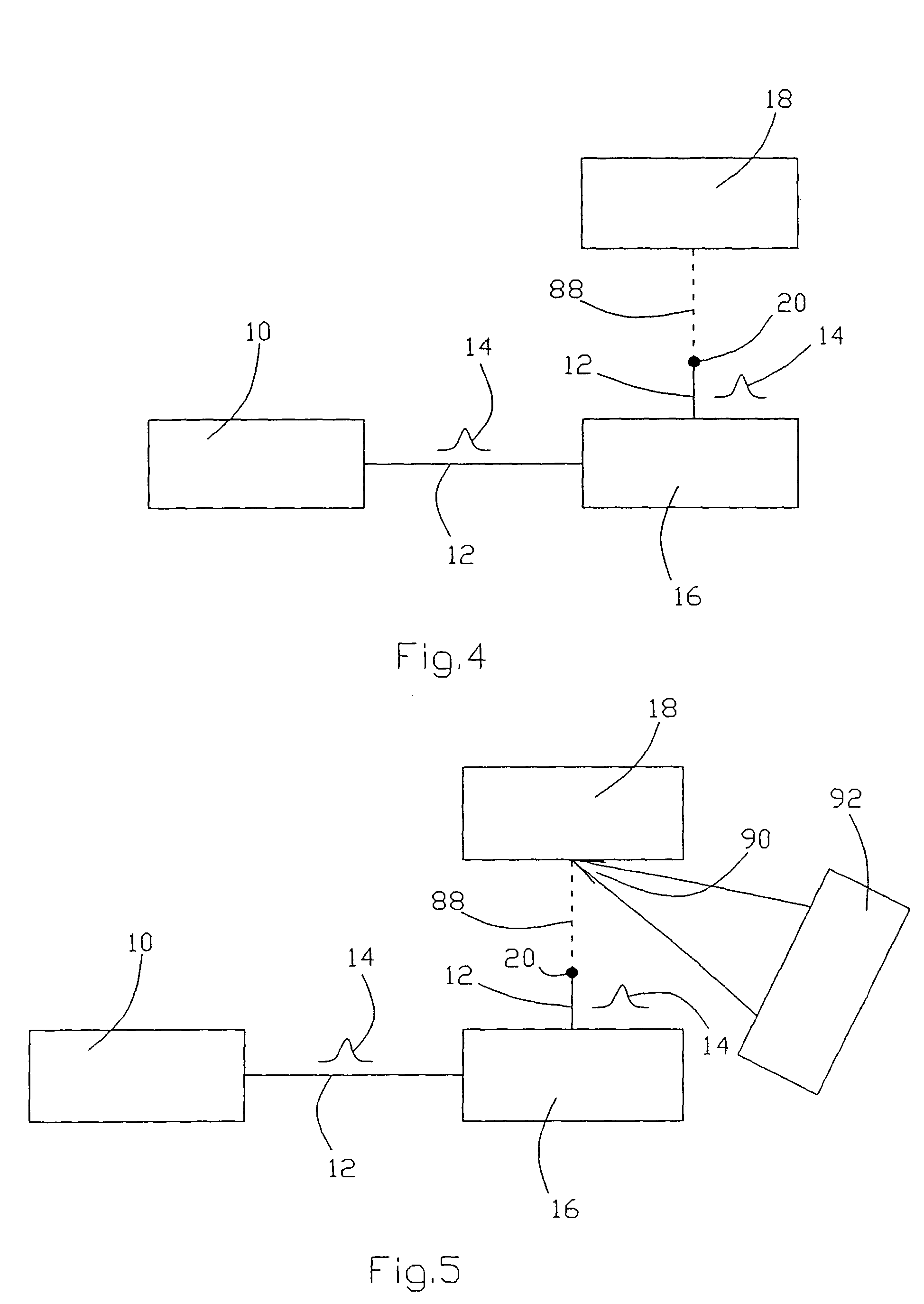
[0051]Referring to FIG. 11, a method of material analysis of an object is described using a material analyzing device according to FIG. 5. Numeral 116 designates a tank for chemicals with a molten mass 118, the material composition of which shall be analyzed. The system 10, 16 (see FIG. 5) for generating the filament 88 and the analyzing device 92 is flanged to the tank for chemicals 116. The filament 88 excites the molten mass 118 to plasma lightening 90 which is analyzed by the analyzing device 92. The level of the tank for chemicals is not critical because the filament 88 provides the energy required for plasma excitation over a long distance.

third embodiment

[0052]In FIG. 12 a method of material analysis of an object is described using a material analyzing device according to FIG. 5. It is the material analysis of objects in an environment which is difficult to access, such as damaged areas. Numeral 120 designates a burning building. It is the object to analyze the materials in this building, for example to determine whether there is a danger by poisonous gases or not. For this purpose the device shown in FIG. 5 is mounted in a moveable container 122. The container is transported to a position near the building 120. The building 120 can be scanned by the filament 88. The filament 88 excites the material to be investigated to plasma lighting 90, which then is analyzed by the analyzing device 92. Thereby a very quick and safe analysis can be carried out.


PUM

PropertyMeasurementUnit
exit poweraaaaaaaaaa
diameteraaaaaaaaaa
distancesaaaaaaaaaa

Abstract

The invention relates to a method for material processing and / or material analysis of an object (18) made from condensed matter by means of a laser (12). A laser pulse (14) is generated by a laser, emitted in the direction of the object. The laser pulse is spatially and temporally focussed such as to give a peak power for the laser pulse at a point between the laser and the object which exceeds the critical power for a self-focussing effect of the laser pulse. The laser pulse thus forms a filament (88) of high power density. The filament (88) is directed at the object and generates an aggregation state change there (evaporation or plasma formation) for a part of the material of the object. The method can be applied to both material processing (cutting, drilling, welding, hardening) and material analysis (analysis of the plasma light).

Description

CROSS REFERENCE TO RELATED APPLICATION[0001]This application is a 35 USC §371 National Phase Entry Application from PCT / EP03 / 02074, filed Feb. 28, 2003, and designating the U.S.TECHNICAL FIELD[0002]The invention relates to a method of material processing and / or material analysis of an object of condensed substance using a laser.[0003]Material processing is understood as a plurality of processing methods, wherein the material undergoes heating or evaporation, for example cutting, drilling, welding or hardening of materials.[0004]In the material analysis which is relevant here a plasma lightening is generated by a laser, and is analyzed in such a way that conclusions can be drawn with respect to the material.[0005]Condensed substance is liquid or solid substance. The evaporation of the substance as well as the generation of a plasma lightening comprises a change of the state of aggregation of the material.PRIOR ART[0006]Various methods of material processing or material analysis using...

Claims


Application Information

Patent Timeline
Patent Type & Authority Patents(United States)
IPC IPC(8): B23K26/00B23K26/04B23K26/06
CPCB23K26/04B23K26/0635B23K26/0624
Inventor WOESTE, LUDGERWOLF, JEAN-PIERRE
Owner FREE UNIV OF BERLIN
Learn More