Apparatus and method for remote beam forming for satellite broadcasting systems

a satellite broadcasting system and satellite technology, applied in the field of satellite broadcasting systems, can solve the problems of inherently limited flexibility and inability to upgrade to keep pace with more advanced ground systems, and achieve the effects of reducing potential distortion effects, improving downlink performance of the system, and distorting the shape of the broadcast beam

Active Publication Date: 2012-01-17
SPATIAL DIGITAL SYST
View PDF6 Cites 27 Cited by
  • Summary
  • Abstract
  • Description
  • Claims
  • Application Information

AI Technical Summary

Benefits of technology

[0007]A satellite broadcasting system is achieved that provides multiple simultaneous downlinks controlled by remote digital beam forming (DBF) processors employed at distributed, ground-based uplink stations. The system enables the formation of configurable downlink radiation patterns covering selected service areas, enables the use of multiple simultaneous downlinks that may carry different content to different geographic regions, and minimizes the impact of differential phase and amplitude drift between uplink signal elements.
[0014]For the case in which M is chosen to be larger than N such that the N-component product vector created in the ground segment is padded by one or more nulls, the cost function unit mentioned above allows calibration and monitoring of the uplink channel, enabling improved downlink performance of the system. When the back-channel signals embedded in the uplinked beam is received and amplified by the satellite system, frequency converted to the broadcast frequency (typically Ku or S band), and run through the wavefront de-multiplexer, the original N data streams (each modulated by corresponding components of the BWV) are recovered, including the M-N null channels. For a completely balanced feeder link with multiple back channels having identical propagation delays and attenuations, the M-N recovered channels will contain no signals. However, in reality, imbalances and differential propagation characteristics among various channels will cause some energy to leak into the null outputs of the wavefront de-multiplexer. By monitoring the null channels, changes can be made dynamically to the amplitudes and phases of the signals entering the wavefront de-multiplexer to correct for these imbalances and to produce true nulls where expected. Alternatively, the null energy monitored by the cost function unit can be downlinked back to the ground segment via a separate backchannel, and the ground segment can accordingly pre-compensate for the measured imbalances by adjusting the amplitudes and phases of the signals emerging from the wavefront multiplexer on the ground segment. Thus, the use of one or more null channels in the uplink enables continuous calibration and monitoring of the uplink channel, assuring that the downlink beams are formed properly and cleanly.
[0015]By contrast, without the wavefront multiplexing feature provided by the present invention, each weighted element signal would propagate through a unique backchannel in the feeder link. The differential propagation characteristics of each channel would modulate the weighted element signals differently in both amplitude and phase. Depending on the frequency band of the feeder link, these effects could significantly distort the shape of the broadcast beam.
[0016]The wavefront multiplexing scheme, however, directs each of the N weighted element signals generated by the remote beam-forming facility on the ground to go through all of the M propagation channels simultaneously and in parallel. Thus, the channel effects are spread across the entire feeder link bandwidth and across all of the N weighted element signals, reducing the potential distortion effects by a factor of the square root of M, or four for the example discussed below having M equal to sixteen.

Problems solved by technology

However, nearly all of such systems are fixed at the time the satellite is launched and cannot be upgraded to keep pace with more advanced ground systems.
Even those systems that maintain some satellite configurability must be controlled by complex systems on board the satellite and thus have inherently limited flexibility.

Method used


Image

  • Apparatus and method for remote beam forming for satellite broadcasting systems
  • Apparatus and method for remote beam forming for satellite broadcasting systems
  • Apparatus and method for remote beam forming for satellite broadcasting systems

Examples


Embodiment Construction

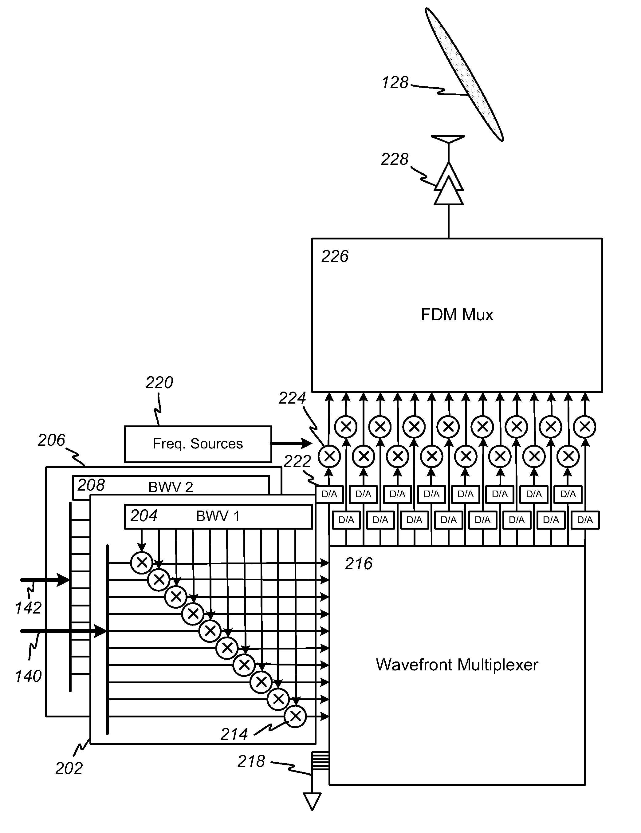
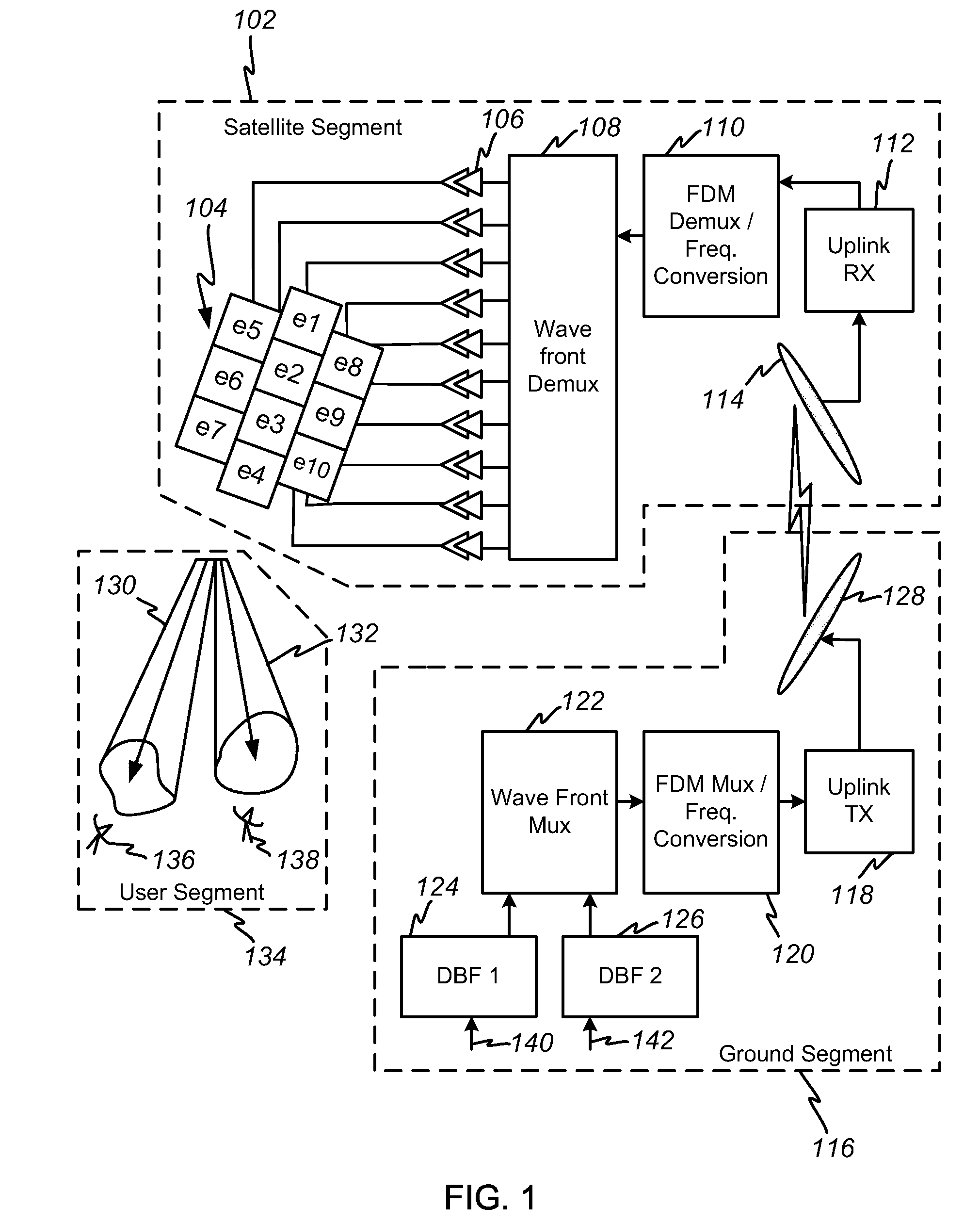
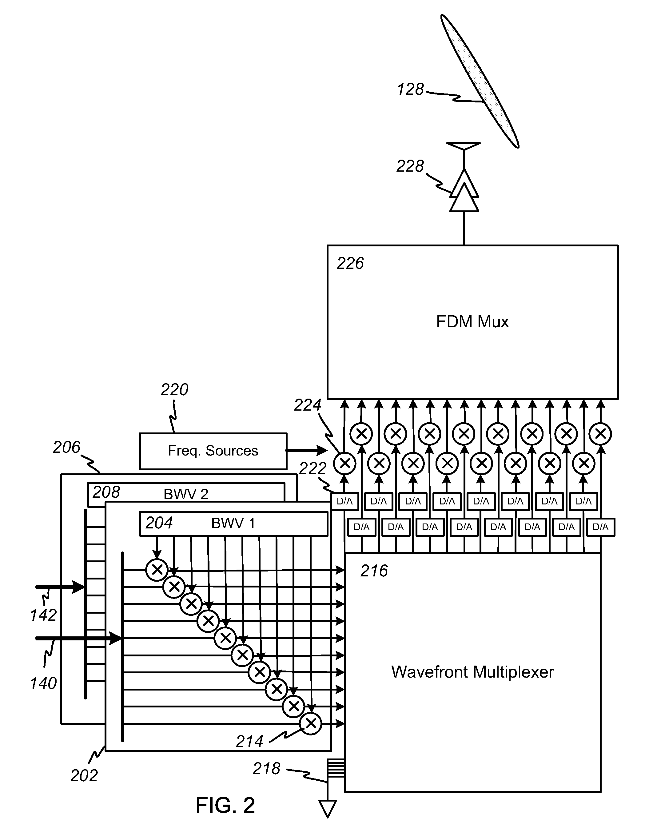
[0022]The invention provides a direct satellite broadcast system that includes a remote ground-based beam-forming facility. Beam-forming information is encoded into audio, video, or other content within the ground-based uplink facility. It is then uplinked to one or more satellites and downlinked via a segmented downlink broadcast antenna array. Beam-forming information encoded on the ground creates multiple downlink beams appearing at the satellite's downlink broadcast antenna array, allowing control over which content is radiated to which ground-based users.

[0023]FIG. 1 depicts a block diagram of a direct broadcast system in accordance with the present invention. The ground segment 116 includes a first digital beam forming (DBF) processor 124 and a second DBF processor 126. Content data 140 enters the first DBF processor 124, and content data 142 enters the second DBF processor 126. The two content streams may be identical or may be distinct, depending on the particular broadcast ...


PUM


Abstract

A satellite broadcasting system is achieved in which remote beam forming processors located among distributed ground stations are used to control downlink beam footprints and pointing directions. Digital beam forming techniques allow a single satellite downlink broadcast antenna array to generate multiple simultaneous downlinks that can be pointed independently and that may contain distinct information content. By allocating some of the uplink back-channel elements as null channels, continuous calibration of the uplink channel can be performed, improving the performance of the downlink broadcast array and the quality of the broadcast for users. By wavefront multiplexing, all of the uplink channel elements propagate through the all of the available propagation channels simultaneously, eliminating the need for complex and costly individual array-element calibration equipment using on-board or ground-based references.

Description

RELATED APPLICATION DATA[0001]This application claims the benefit, pursuant to 35 U.S.C. §119(e), of U.S. provisional application Ser. No. 60 / 930,943, filed May 21, 2007.BACKGROUND OF THE INVENTION[0002]1. Field of the Invention[0003]The present invention relates to satellite-based broadcasting systems. More particularly, it relates to systems for downlinking broadcast content data from satellites that are linked to ground-based uplink stations having remote beam-forming capability.[0004]2. Description of Related Art[0005]Systems for broadcasting audio and video data from satellites in geostationary orbit (GEO), medium-Earth orbit (MEO), and low-Earth orbit (LEO) to ground-based users are well known in the art. Such systems generally rely on one or more ground-based uplink facilities to uplink content to the satellite. The satellite then downlinks the content to individual users in selected geographical areas. Some systems employ shaped reflectors to develop a downlink beam pattern ...

Claims


Application Information

Patent Timeline
Patent Type & Authority Patents(United States)
IPC IPC(8): H04B7/185
CPCH04B7/2041H04N7/20H04W16/14H04L27/265H04B7/1851
Inventor CHANG, DONALD CHIN-DONG
Owner SPATIAL DIGITAL SYST
Why Eureka
Try Eureka