
Maintenance mechanism for lighting equipment in a closed space of high radiation activity

a maintenance mechanism and lighting equipment technology, applied in lighting and heating equipment, furniture, instruments, etc., can solve the problems of insufficient negative pressure, inconvenience in maintenance work, limited product life of lighting equipment, etc., and achieve the effect of reducing radiation exposure for workers and shortening operation tim

Inactive Publication Date: 2012-01-24
INST NUCLEAR ENERGY RES ROCAEC
View PDF2 Cites 2 Cited by
  • Summary
  • Abstract
  • Description
  • Claims
  • Application Information

AI Technical Summary

Benefits of technology

This mechanism reduces worker radiation exposure and shortens maintenance time by enabling external access and sealing to maintain equipment without compromising radiation shielding or air pressure.

Problems solved by technology

However, lighting equipment only has a limited product life.
Therefore, replacing lighting equipment may cause inconvenience.
This causes inconvenience for the maintenance work.
Besides, maintenance workers entering the closed space of high radiation activity need to open the entrance, which is not only time-consuming and laborious but also likely to cause insufficient negative pressure for the closed space of high radiation activity and radiation leak.
Complicated protective measures also impose much inconvenience to the operation of lighting maintenance, repair and adjustment.

Method used


Image

  • Maintenance mechanism for lighting equipment in a closed space of high radiation activity
  • Maintenance mechanism for lighting equipment in a closed space of high radiation activity
  • Maintenance mechanism for lighting equipment in a closed space of high radiation activity

Examples


Embodiment Construction

[0016]To achieve the above objectives, the technical approaches and the performance for the present invention are described by the following preferred embodiments with illustrative figures, so the examiners can get complete understanding.

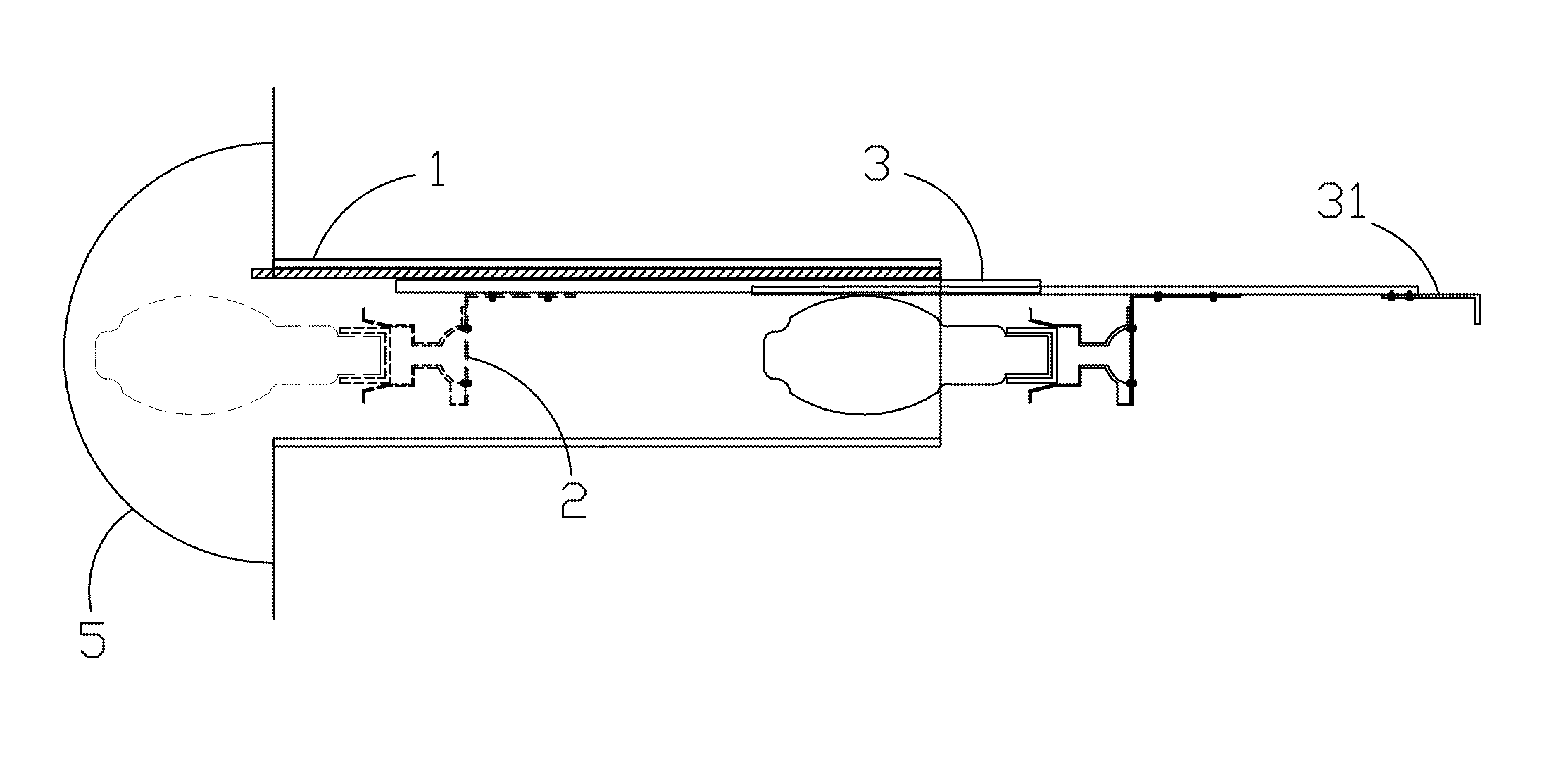
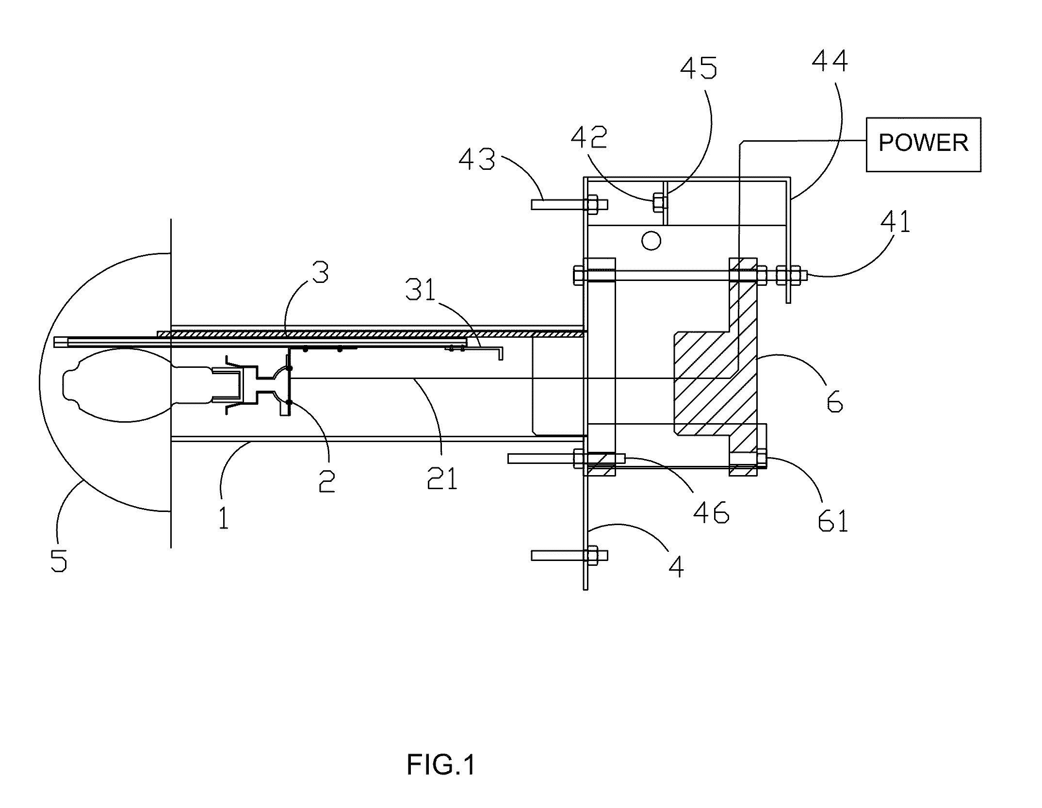
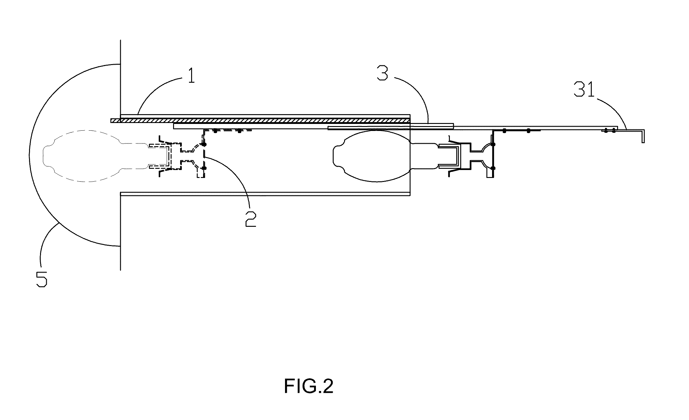
[0017]Please refer to the figures from FIG. 1 to FIG. 3. FIG. 1 is the cross-sectional structural diagram for the present invention and the structure comprises a passage 1, a lamp base 2, a multi-section slide rail 3, a lighting handle 31, a stainless steel fixation plate 4, a lead glass lamp guard 5 and a convex lead plug 6. In the passage 1, there is a multi-section slide rail 3; and on the passage 1, there is a lamp base 2 to carry lighting equipment or camera.

[0018]In the bottom of the lamp base 2, there is an electric wire 21 that goes out through the convex lead plug 6 to connect to external power source. In the maintenance hole at a side of the passage 1, there is a stainless steel fixation plate 4 that is fixed onto the wall by fixation plat...


PUM

PropertyMeasurementUnit
thicknessaaaaaaaaaa
radiation absorbanceaaaaaaaaaa
rigidityaaaaaaaaaa

Abstract

The main objective of the present invention is to provide maintenance mechanism for lighting equipment in a closed space of high radiation activity, which comprises a passage, a lamp base, a multi-section slide rail, a lighting handle, a stainless steel fixation plate, a lead glass lamp guard and a convex lead plug. On the top side of the passage there is a multi-section slide rail with the lamp base attached to move the lamp. The maintenance hole at the end of the passage has a convex lead plug and a stainless steel fixation plate. When the hole closes, the convex lead plug is locked to the lead plug positioning screw under the stainless steel fixation plate; while the maintenance hole opens, on the top right and top left of the stainless steel fixation plate there is a L-shaped short iron plate and a L-shaped long iron plate respectively. On the L-shaped long iron plate there is an axial screw as the axis for the convex lead plug to move and rotate. On the L-shaped short iron plate there is a lead plug positioning screw for the convex lead plug after being pulled out to have temporary fixation. At the radiation space end of the passage there is a semi-circular lead glass lamp guard for the shielding wall to be fixed without moving with the lighting equipment.

Description

BACKGROUND OF THE INVENTION[0001]1. Field of the Invention[0002]The present invention is related to a maintenance mechanism for the lighting equipment in a closed space of high radiation, especially a simple mechanism for applications in the maintenance of lighting or camera equipment in a closed space of high radiation activity to effectively reduce the exposure of maintenance workers to radiation.[0003]2. Description of the Prior Art[0004]In a closed space of high radiation activity it usually needs appropriate lighting to assist in the operation of camera monitoring system. However, lighting equipment only has a limited product life. Therefore, replacing lighting equipment may cause inconvenience. There is usually a certain thickness for the protective shield for a closed space of high radiation activity. Maintenance workers entering the closed space of high radiation activity need to wear thick and heavy protective clothing (lead apron) to reduce radiation absorbance and prevent...

Claims


Application Information

Patent Timeline
Patent Type & Authority Patents(United States)
IPC IPC(8): G03B17/00C21B7/24
CPCF21V19/04F21V25/12G03B17/00
Inventor HUANG, CHI-WENCHU, HSIN-CHIWU, BING-RONG
Owner INST NUCLEAR ENERGY RES ROCAEC
Learn More