Discharge controller

a discharge controller and discharge voltage technology, applied in the direction of secondary cell servicing/maintenance, electrochemical generators, safety/protection circuits, etc., can solve the problems of deterioration of positive electrodes or negative electrode materials, and etc., to suppress the deterioration of cycle deterioration in performances, improve the utilization efficiency of energy as stored, and suppress the effect of deteriora

Inactive Publication Date: 2012-01-24
GK BRIDGE 1
View PDF13 Cites 7 Cited by
  • Summary
  • Abstract
  • Description
  • Claims
  • Application Information

AI Technical Summary

Benefits of technology

[0021]It is an object of the present invention to provide a discharge controller which offers an improved utilization efficiency of energy as stored with ease by suppressing a drop in lower limit voltage of discharge while suppressing deterioration in cycle deterioration in performances of a secondary battery.
[0022]A discharge controller according to one aspect of the present invention includes a secondary battery, a switch section for opening and closing a discharge path from the secondary battery to a load, a voltage detector for detecting a terminal voltage of the secondary battery, and a cut-off voltage control section for controlling the switch section to be opened when the terminal voltage as detected by the voltage detector is at or below a predetermined cut-off voltage of discharge VE, and while measuring an amount of decrease per unit time of the terminal voltage as detected by the voltage detector to set the cut-off voltage of discharge VE to a lower voltage, for a larger amount of decrease per unit time of the terminal voltage as detected by the voltage detector.
[0023]According to the foregoing structure, the discharge of the secondary battery is stopped when the terminal voltage of the secondary battery is reduced to not more than the cut-off voltage of discharge VE. Moreover, when the cut-off voltage of discharge VE is set by the cut-off voltage control section such that the large is the amount of decrease per unit time, the lower is the cut-off voltage of discharge VE. With this structure, in the case where respective polarizations of the positive and negative electrodes increase as a result of discharging the secondary battery with a large current, an amount of decrease per unit time increases. As a result, the cut-off voltage control section reduces the cut-off voltage of discharge VE corresponding to an increase in polarizations of the positive and negative polarities. It is therefore possible to improve the utilization efficiency of energy as stored by reducing the cut-off voltage of discharge VE while suppressing the cycle deterioration of the secondary battery.
[0024]In the case where the polarizations of positive and negative electrodes are reduced as a result of discharging the secondary battery with a low current, an amount of decrease in voltage per unit time is reduced. As a result, the cut-off voltage control section increases the cut-off voltage of discharge VE corresponding to a decrease in polarizations of the positive and negative polarities. It is therefore possible to suppress the deterioration of the secondary battery by terminating the discharge before the deterioration in the cycle performance occurs without being affected by an increase in voltage resulting from the deterioration in cycle performances caused by a decrease in polarizations of the positive and negative polarities.

Problems solved by technology

When adopting such lithium-ion secondary battery; however, the following problem may arise.
That is, when the terminal voltage becomes too low as a result of discharging, an irreversible chemical reaction may occur inside the battery, which causes drastic deteriorations of the battery performance.
Such reduction in capacity is called cycle deterioration, which is the problem associated with the life of the secondary battery.
One of the causes for the deterioration of the secondary battery can be a discharge of a terminal voltage to or below the lower limit discharge voltage, which in turn causes a deterioration of the positive electrode or the negative electrode material in the last stage of discharge.
When adopting for the positive electrode, an active material having a α-NaFeO2 type layer evaporitic structure represented by cobaltic acid, an irreversible reaction would start at a potential of not higher than 1.5 V with respect to lithium potential, which would result in cycle deterioration of the positive electrode.
Further, when charging once again the battery that reaches the melting potential of the copper, a small short-circuit and an increase in resistance of the cell would occur due to the copper deposited to the positive electrode side, resulting in a rapid cycle deterioration.
However, when adopting the foregoing method of controlling the cut-off voltage of discharge, in the case where the discharge current value is increased, the cell voltage may reach the lower limit value as set due to the generation of polarity, despite of that the respective potentials of the positive electrode and the negative electrode have not reached the potentials at which the positive electrode and the negative electrode deteriorate.
However, when adopting the means for varying the cut-off voltage of discharge according to the discharge current as disclosed in Patent Document 1, it is not possible to terminate the discharge at an optimal voltage, and a rapid cyclic deterioration occurred or the battery capacity of sufficient level could not be achieved depending on environmental temperature.
When changing the cut-off voltage of discharge only based on the discharge current value, a problem arises in that the discharge is terminated before discharging the charges to a sufficient level, or rapid cycle deterioration occurs due to over-discharge.

Method used


Image

  • Discharge controller
  • Discharge controller
  • Discharge controller

Examples


first embodiment

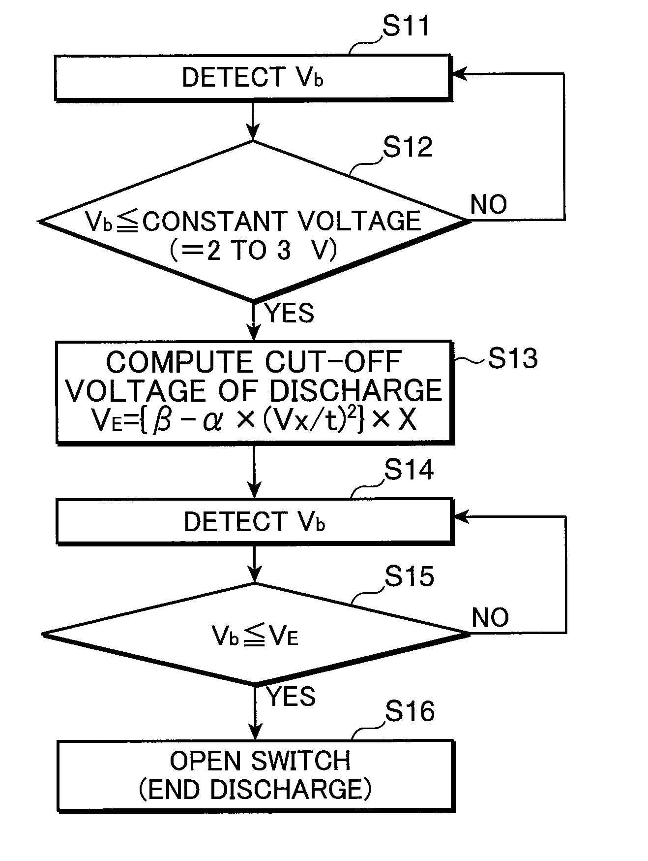
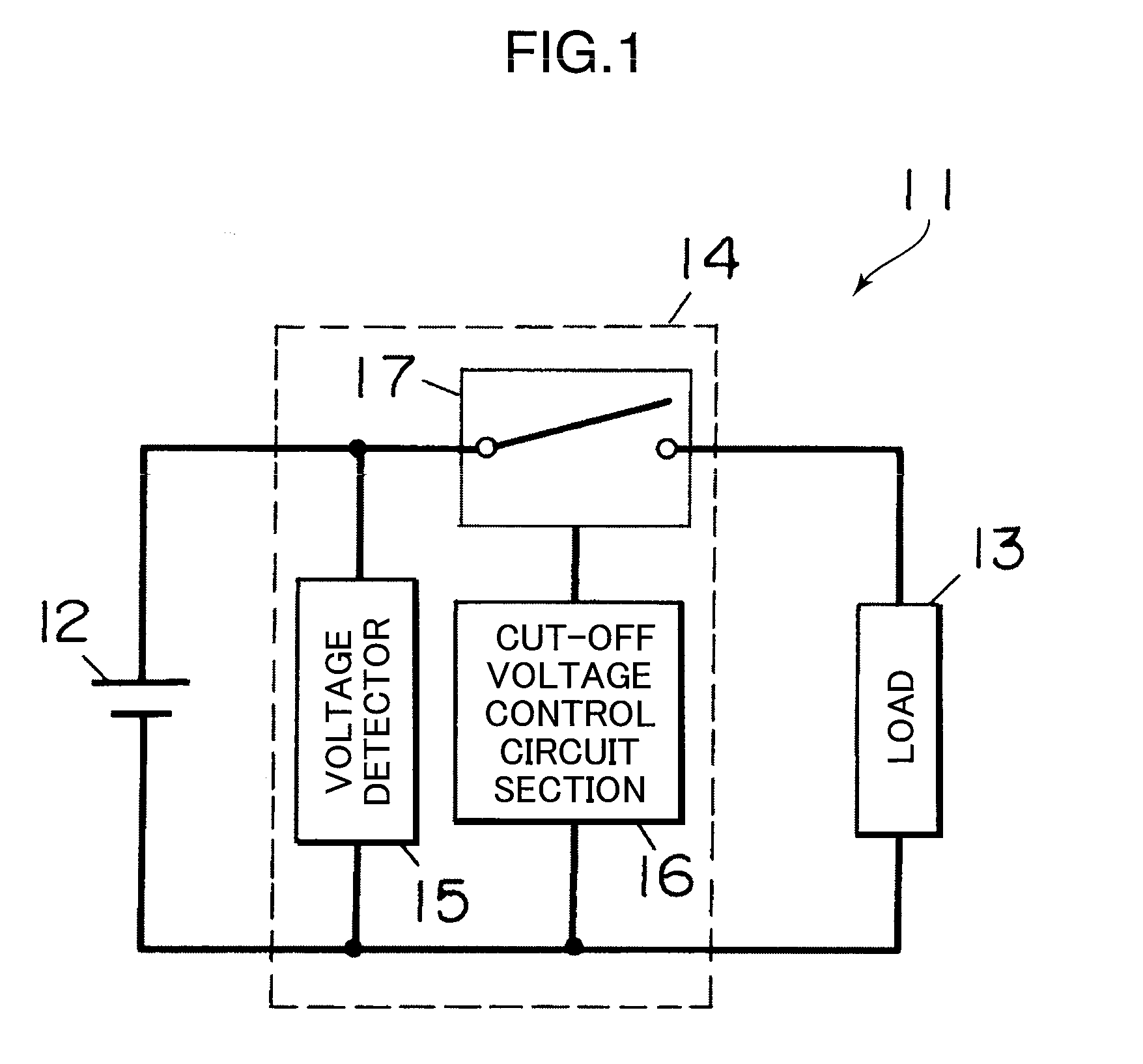
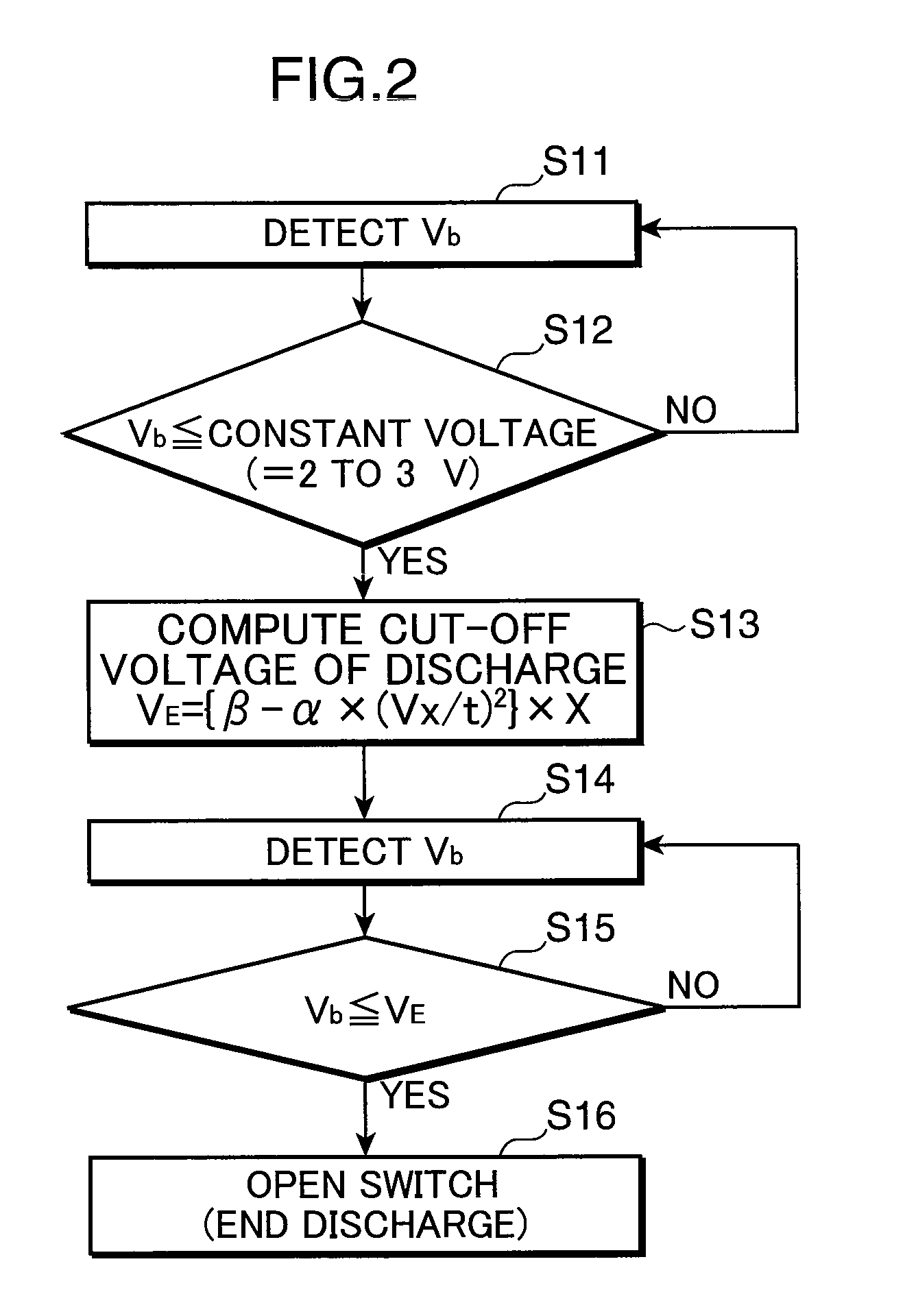
[0029]The following descriptions explain the first embodiment with reference to FIG. 1. A discharge controller in accordance with the first embodiment of the present invention includes a secondary battery 12, a load 13, and a controller 14 which are connected as shown in FIG. 1. It should be noted here that the load 13 can be disconnected while discharge is not performed. The discharge controller shown in FIG. 1 is suited in applications wherein discharge is performed using a large discharge current of a wide range, in the case of, for example, adopting a heavy load equipment as a load 13, such as a power tool, an electric scooter, assistance bicycle, or the like.

[0030]The secondary battery 12 is a lithium-ion secondary battery using the nonaqueous-electrolyte. The secondary battery 12 may be arranged such that a plurality of cells are connected in series or in parallel, are connected in series and parallel. Incidentally, the number of batteries (cells) to be connected is not partic...

example 1

[0069]The following will provide examples for the nonaqueous-electrolyte secondary battery and the discharge controller adopting the same as a power supply in accordance with one embodiment of the present invention.

[0070]After baking Li2CO3, CO3O4, NiO, and MnO2, these materials were mixed to have a composition of LiNi0.33Mn0.33Co0.33O2. The resulting composition LiNi0.33Mn0.33Co0.33O2 was then baked for ten hours at 900° C. to obtain a positive electrode active material. 100 parts by weight of the resulting positive electrode active material were kneaded with 2.5 parts by weight of the acetylene black, 4 parts by weight of the fluoroplastics binder, and an appropriate amount of carboxymethylcellulose solution using the Double Arm Kneader, thereby producing positive electrode paste.

[0071]The resulting positive electrode paste was then applied onto both surfaces of the aluminum foil with a thickness of 30 μm and then dried. The positive electrode paste was then rolled to have a thick...


PUM


Abstract

A discharge controller includes a secondary battery, a switch section for opening / closing a discharge path from the secondary battery to a load, a voltage detector for detecting a terminal voltage of the secondary battery, and a cut-off voltage control section for controlling the switch section to be opened when the terminal voltage as detected by the voltage detector is not more than a predetermined cut-off voltage of discharge VE, while measuring an amount of decrease per unit time of the terminal voltage as detected by the voltage detector to set the cut-off voltage of discharge VE to a lower voltage, for a larger amount of decrease per unit time of the terminal voltage as detected by the voltage detector.

Description

RELATED APPLICATIONS[0001]This application is the U.S. National Phase under 35 U.S.C. §371 of International Application No. PCT / JP2007 / 068406, filed on Sep. 21, 2007, which in turn claims the benefit of Japanese Application No. 2006-274916, filed on Oct. 6, 2006, the disclosures of which Applications are incorporated by reference herein.FIELD OF THE INVENTION[0002]The present invention relates to a discharge controller adopting a nonaqueous-electrolyte secondary battery, for use in heavy load equipment, an electric vehicle or other transport aircraft machines which require large capacity and long life.DESCRIPTION OF THE RELATED ART[0003]In recent years, with developments of electronic technologies, heavy load equipments, or electric vehicle or other transport aircraft machines of smaller in size and lighter in weight have been developed. With this development, secondary batteries of higher energy density and longer life have been demanded. For the secondary batteries to be used in t...

Claims


Application Information

Patent Timeline
Patent Type & Authority Patents(United States)
IPC IPC(8): H02J7/00
CPCH01M10/0525H01M10/448H01M10/48H02J7/0031H02J2007/004Y02E60/122H02J7/00306Y02E60/10H01M10/44H02J7/007184H01M10/443H01M10/482
Inventor MURAOKA, YOSHIYUKINAKAI, HARUYA
Owner GK BRIDGE 1
Why Eureka
Try Eureka