Fluorescent endoscopic device and method of creating fluorescent endoscopic image

a fluorescence endoscopic and endoscopic image technology, applied in the field of fluorescence endoscopic devices and creating fluorescent endoscopic images, can solve the problems of difficult discrimination between normal tissue and lesion tissue, s/n of calculated image on the basis of obtained calculation value also becomes extremely low,

Active Publication Date: 2012-01-31
OLYMPUS CORP
View PDF11 Cites 3 Cited by
  • Summary
  • Abstract
  • Description
  • Claims
  • Application Information

AI Technical Summary

Problems solved by technology

Therefore, if standardized calculation is carried out using such a fluorescent image, the S / N of a calculated image on the basis of an obtained calculation value also becomes extremely low, and discrimination between a normal tissue and a lesion tissue becomes extremely difficult.

Method used


Image

  • Fluorescent endoscopic device and method of creating fluorescent endoscopic image
  • Fluorescent endoscopic device and method of creating fluorescent endoscopic image
  • Fluorescent endoscopic device and method of creating fluorescent endoscopic image

Examples


embodiment 1

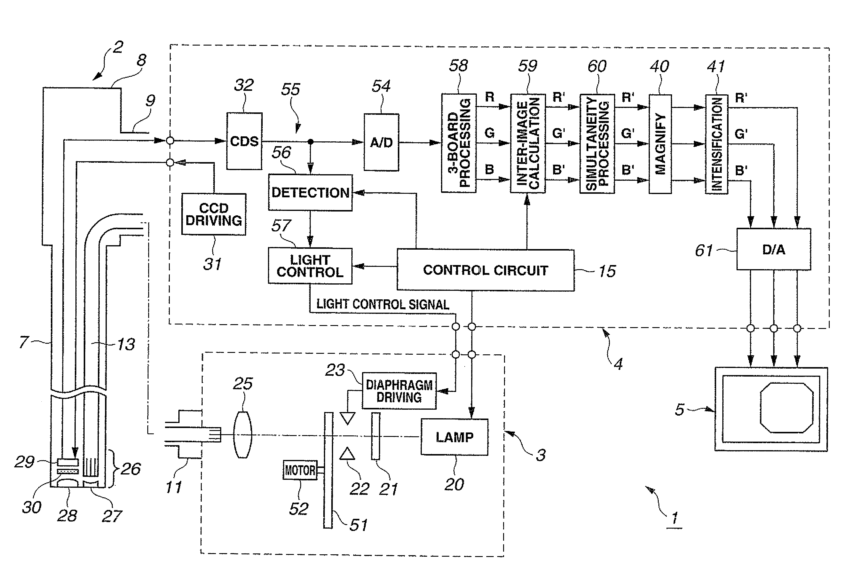
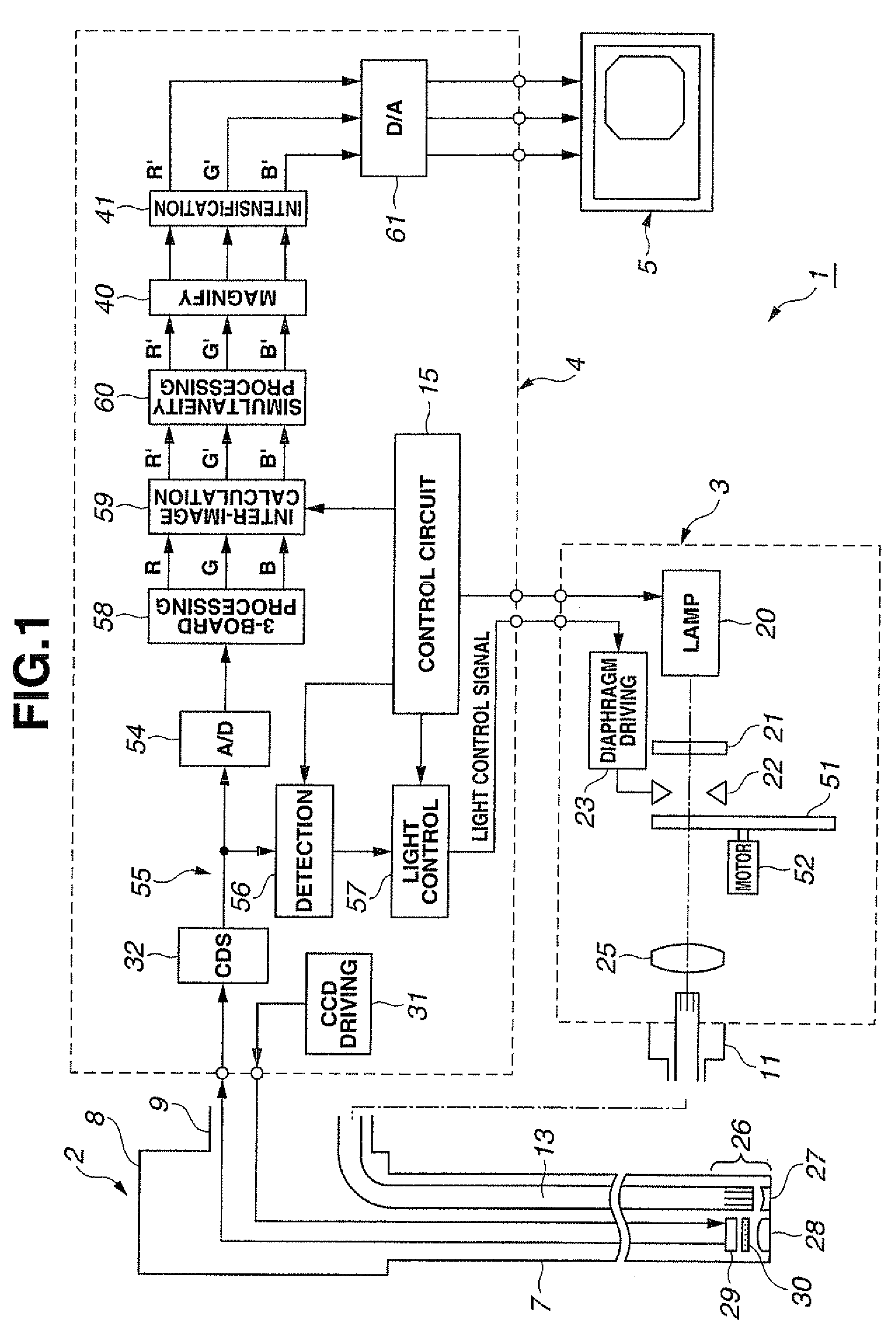
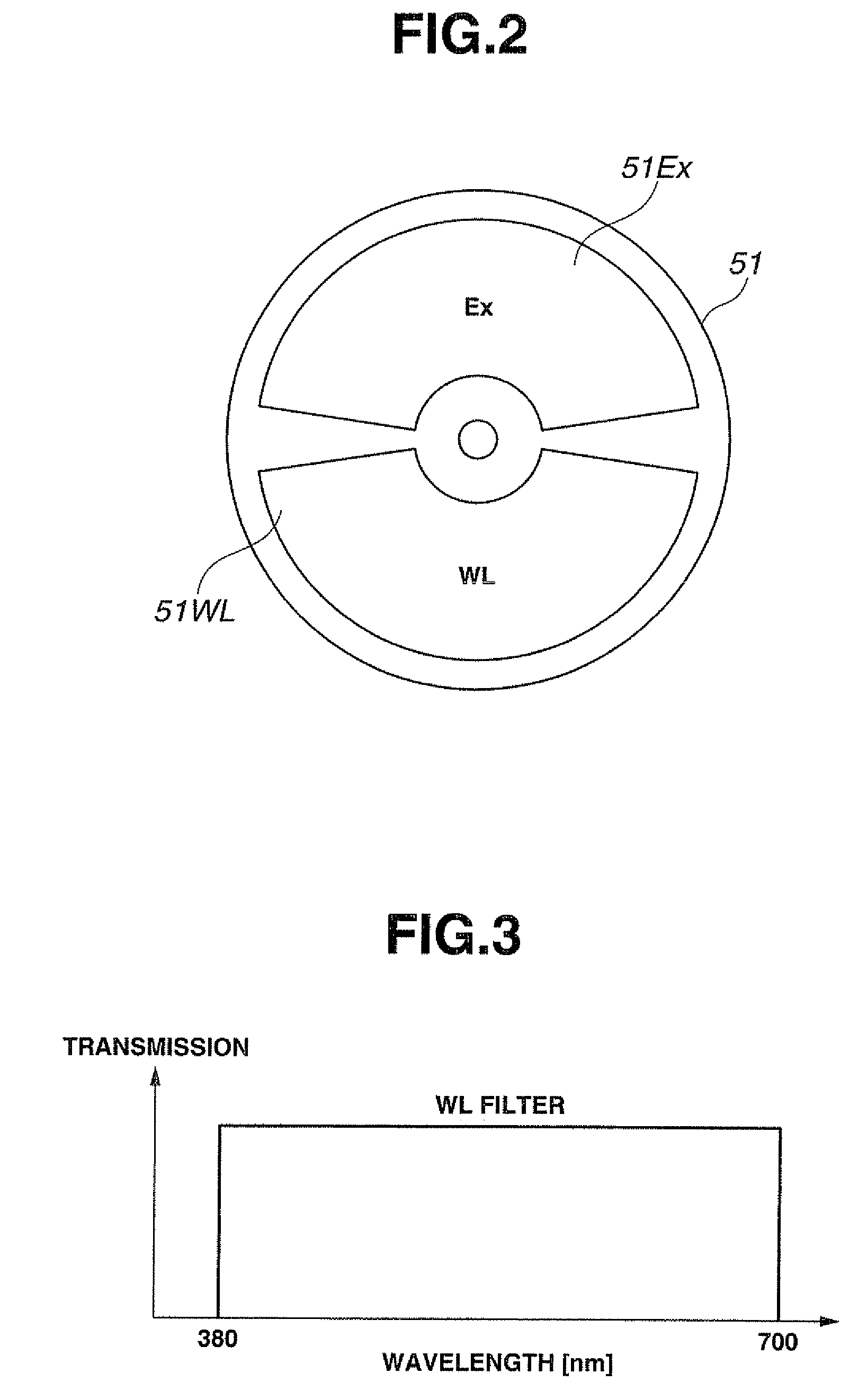
[0035]FIGS. 1 to 12 relate to an embodiment 1 of the present invention, in which FIG. 1 is a configuration diagram illustrating configuration of a fluorescent endoscopic device, FIG. 2 is a diagram illustrating configuration of a rotating filter in FIG. 1, FIG. 3 is a diagram illustrating a transmission characteristic of a WL filter in FIG. 2, FIG. 4 is a diagram illustrating a transmission characteristic of an EX filter in FIG. 2, FIG. 5 is a diagram illustrating a transmission characteristic of excitation light cut filter in FIG. 1, FIG. 6 is a diagram illustrating a Bayer-arrayed color filter arranged on an image pickup face of a CCD in FIG. 1, FIG. 7 is a diagram illustrating a transmission characteristic of the color filter in FIG. 6, FIG. 8 is a block diagram illustrating configuration of an inter-image calculation portion in FIG. 1, FIG. 9 is a diagram illustrating timing of image data of the inter-image calculation portion and a simultaneity portion in FIG. 1, FIG. 11 is a f...

embodiment 2

[0078]FIGS. 13 to 23 relate to an embodiment 2 of the present invention, in which FIG. 13 is a configuration diagram illustrating configuration of a fluorescent endoscopic device, FIG. 14 is a diagram illustrating configuration of the rotating filter in FIG. 13, FIG. 15 is a diagram illustrating a transmission characteristic of a G filter in FIG. 14, FIG. 16 is a diagram illustrating a transmission characteristic of an EX1 filter and an EX2 filter in FIG. 14, FIG. 17 is a diagram illustrating a transmission characteristic of an excitation light cut filter in FIG. 13, FIG. 18 is a diagram for explaining an action of a fluorescent endoscopic device in FIG. 13, FIG. 19 is a block diagram illustrating configuration of an inter-image calculation portion in FIG. 13, FIG. 20 is a diagram illustrating timing of image data of each portion of the fluorescent endoscopic device in FIG. 13, FIG. 21 is a block diagram illustrating configuration of an inter-image calculation portion in a first var...


PUM


Abstract

An inter-image calculation portion includes a switch circuit made up of three switch portions for switching each of three image data (R, G, B) from a 3-board processing portion, a first divider, a second divider, a first adder, a second adder, a first LUT, a second LUT, a first clip portion, and a second clip portion. The inter-image calculation portion executes addition processing of two different fluorescent images with two different wavelength bands and division processing the two different fluorescent images with two different wavelength bands and then it executes addition processing which adds the addition results and the division results of the two different fluorescent images with two different wavelength bands or it executes subtraction processing which subtracts the addition results from the division results of the two different fluorescent images with two different wavelength bands.

Description

[0001]This application claims benefit of Japanese Application No. 2008-046648 filed in Japan on Feb. 27, 2008, the contents of which are incorporated herein by this reference.BACKGROUND OF THE INVENTION[0002]1. Field of the Invention[0003]The present invention relates to a fluorescent endoscopic device and a method of creating a fluorescent endoscopic image for diagnosing a normal tissue and a lesion tissue by obtaining a reflection light image and a fluorescent image.[0004]2. Description of the Related Art[0005]Recently, endoscopes have been widely used in the medical field and the industrial field. Particularly, in the medical field, proposals have been made on technologies for obtaining an image in which a normal tissue and a lesion tissue can be easily discriminated in addition to endoscopic devices for obtaining usual images by usual white light.[0006]For example, using a nature that a normal tissue and a lesion tissue emit different fluorescent intensity of auto-fluorescence i...

Claims


Application Information

Patent Timeline
Patent Type & Authority Patents(United States)
IPC IPC(8): A61B1/06A61B5/05
CPCA61B1/00009A61B1/043A61B1/0638A61B5/0071A61B5/0075A61B5/0084A61B1/0646A61B1/0655
Inventor YAMAZAKI, KENJI
Owner OLYMPUS CORP
Why Eureka
Try Eureka