Hydraulic power generator

a generator and hydrostatic technology, applied in the direction of electric generator control, machine/engine, reaction engine, etc., can solve the problems of vibration in the rotor, the moisture situation in the submerged water system will be even more difficult to manage, and the commercial unit is experiencing problems today

Inactive Publication Date: 2012-01-31
CARR FRED K
View PDF5 Cites 37 Cited by
  • Summary
  • Abstract
  • Description
  • Claims
  • Application Information

AI Technical Summary

Benefits of technology

[0027]A further objective of the invention is to provide a variable pitch rotor blade where he pitch of the blade relative to the flow of water can be adjusted and maintain determining the amount of kinetic energy removed from the flowing water.

Problems solved by technology

Problems with lubricating gear boxes have been known for years, and the problem is being experienced in commercial units today.
It is anticipated that the moisture situation in submerged water systems will be even more difficult to manage.
Both wind and water currents have turbulence which can cause vibrations in the rotors.
These vibrations are often transferred through the gear box to the generator resulting in damage.

Method used


Image

  • Hydraulic power generator
  • Hydraulic power generator
  • Hydraulic power generator

Examples


Embodiment Construction

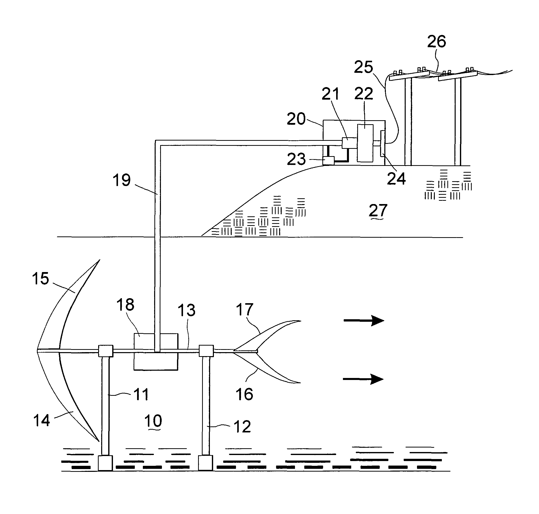
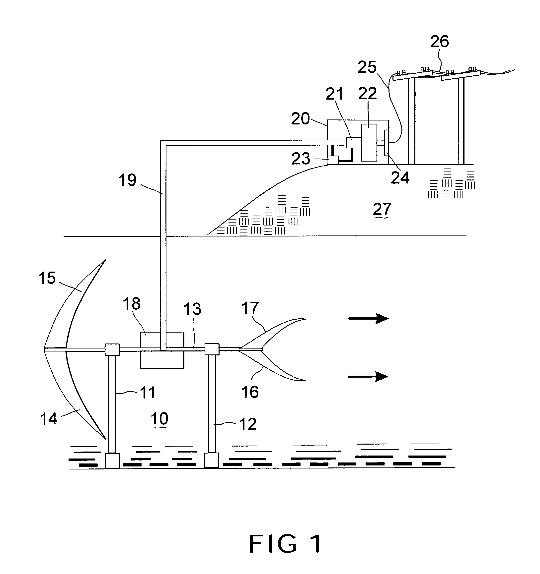
[0032]Referring now to the drawings, and first to FIG. 1, there is shown a schematic view of a hydrokinetic electrical power generating system, generally designated 10, positioned in a flowing current moving from the right to the left as indicated by the arrows. The system is positioned and maintained in the water current by support columns 11,12 which in the illustration are anchored in the seabed. However, the support frames 11,12 may be attached other ways known to those skilled in the art including existing structures as bridges and docks as well as floating structures as ships and barges. When taken together, these constitute a support means.

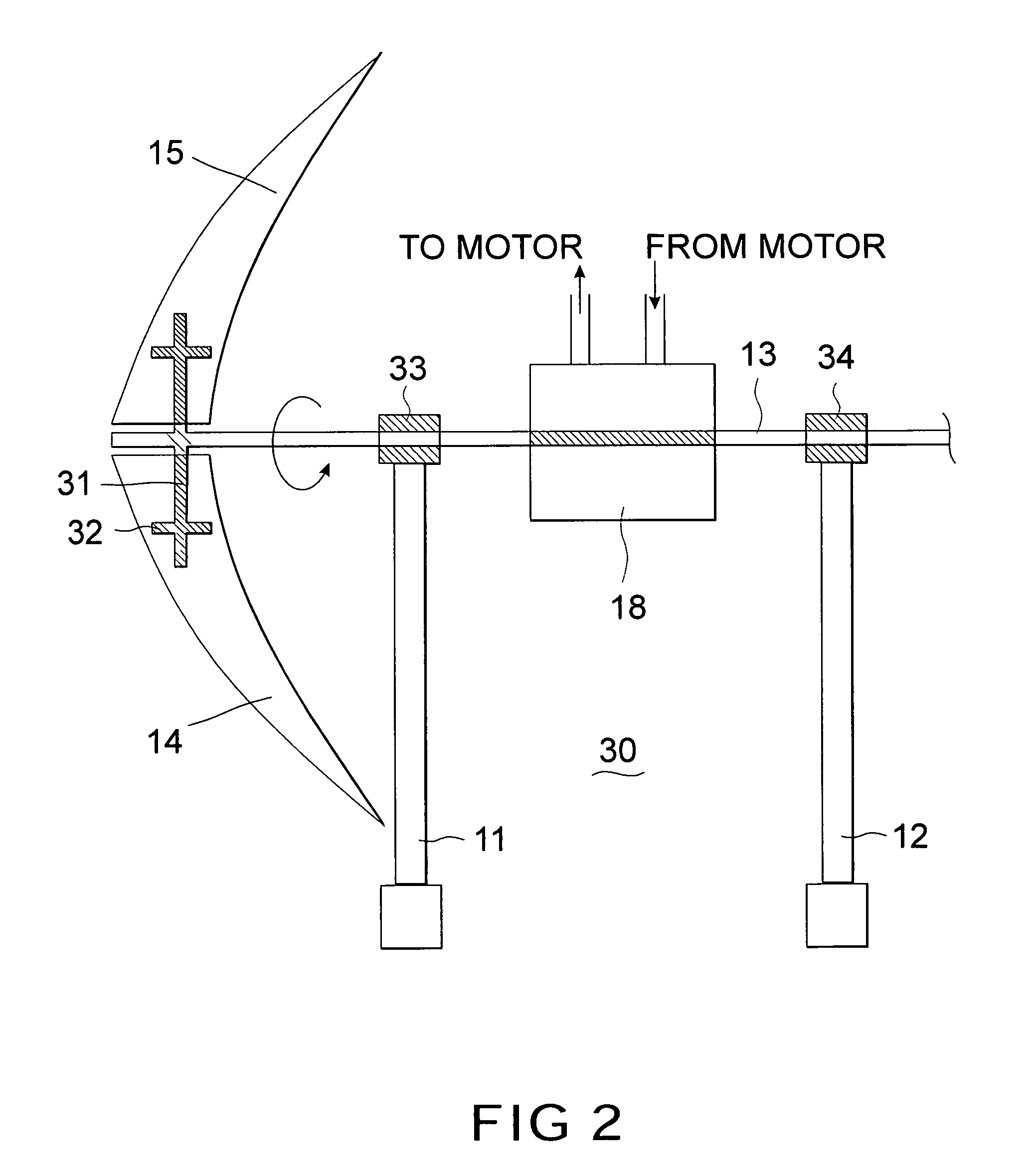
[0033]A rotor shaft 13 is functionally connected to the support columns 11,12 in a manner allowing the rotor shaft 13 to rotate. In the illustration four rotor blades 14,15,16,17 are attached to the rotor shaft 13 where two counter-balanced blades 14,15 are attached on a front end of rotor shaft 13 and two other counter-balanced blades 16,1...


PUM


Abstract

The rotor shaft of an electrical power generator, placed in a wind or water current whereby the kinetic energy causes the rotor shaft to rotate, turns a hydraulic pump generating a hydraulic pressure. The hydraulic pressure is directed to a hydraulic generator motor coupled to an electrical generator. The hydraulic pressure causes the hydraulic motor to turn which spins the generator generating electricity which is transferred to an electric grid for distribution. The generator can be distantly located from the rotors and rotor shaft, for example, on the ground adjacent to the support tower supporting the rotors and rotor shaft.

Description

BACKGROUND OF THE INVENTION[0001]1. Field of the Invention[0002]The present invention relates to the generation of electrical power by wind and water electrical generating systems where a rotor shaft, being rotated by turbine blades, powers a hydraulic pump generating hydraulic pressure which is used to turn a hydraulic generator motor which spins a generator for generating electricity for distribution by an electric grid.[0003]2. Description of the Prior Art[0004]There has recently been a surge of interest in alternate energy sources for generating electricity by both the public and by the utility companies. The public's concern is pollution and the eventual depletion of carbon-based fuels; the utilities are concerned with the state and federal mandates requiring a higher percentage of their electricity output be produced from alternate energy sources. Solar, wind, and biomass are the main alternate energy sources now being purchased by the utilities. Residential solar has been aro...

Claims


Application Information

Patent Timeline
Patent Type & Authority Patents(United States)
IPC IPC(8): F03B13/12F03B3/06
CPCF03B13/00F03B17/061F03D15/00F03D9/28F05B2210/16Y02E10/72Y02E10/28F05B2260/406F03D9/255F03D13/20Y02E10/30Y02E10/20
Inventor CARR, FRED K.
Owner CARR FRED K
Why Eureka
Try Eureka