Identification code circuit for receiving coil in magnetic resonance imaging system

a technology of identification code and receiving coil, which is applied in the field of magnetic resonance imaging (mri), can solve the problems of inability to exchange, complicated identification code situations, and sometimes complicated combination of sub-coils and main coils, and achieve the effect of saving costs and simple realization

Inactive Publication Date: 2012-01-31
SIEMENS HEALTHCARE GMBH
View PDF7 Cites 2 Cited by
  • Summary
  • Abstract
  • Description
  • Claims
  • Application Information

AI Technical Summary

Benefits of technology

[0014]An object of the present invention is to provide an identification code circuit for a receiving coil of a magnetic resonance imaging system, which aiming at the combination of a sub-coil and a main coil, can generate a receiving coil identification code in a simply way on the precondition of saving costs.
[0023]The identification code circuit according to the present invention, by closing the sub-coil switch when the sub-coil is connected to the main coil, makes the values of the regulating resistance and the fixed resistance add together so as to form a combined resistance value. The voltage value across the combined resistance value is different from the voltage value when the main coil is not connected with the sub-coil. Therefore, after the main coil is connected with the sub-coil, the identification code is changed, so the system can identify the different receiving coil combinations according to the different identification codes. Since the identification code circuit according to the present invention does not need to increase the system plugs and sockets, it saves costs, and the change in the resistance value leads to the change in the identification code, so its realization is very simple.

Problems solved by technology

When scanning different parts of a human body, usually dedicated receiving coils are needed and they cannot be exchanged.
The combination of the sub-coil and the main coil sometimes can be very complicated, such as a head receiving coil is the main coil.
In order to distinguish the above different use conditions, an identification code will have to be set for each condition, and then the situations for the identification codes become very complicated.
Although this solution is simple to implement, due to the high costs of the system plugs, the increase in the number of the system plugs is equivalent to the increase of the production costs of the receiving coils, and also the system needs correspondingly more sockets to meet the needs of the increased number of system plugs, thus leading to greatly increased system costs.
Although this method still allows the sub-coil to be connected to the system via the main coil and it saves costs, the design of the oscillating circuit itself is quite complicated.
Currently, regarding the combination of the sub-coil and the main coil, there is not yet a solution that is not only cost-effective but also simple in realizing the generation of the identification codes.

Method used


Image

  • Identification code circuit for receiving coil in magnetic resonance imaging system
  • Identification code circuit for receiving coil in magnetic resonance imaging system
  • Identification code circuit for receiving coil in magnetic resonance imaging system

Examples


first embodiment

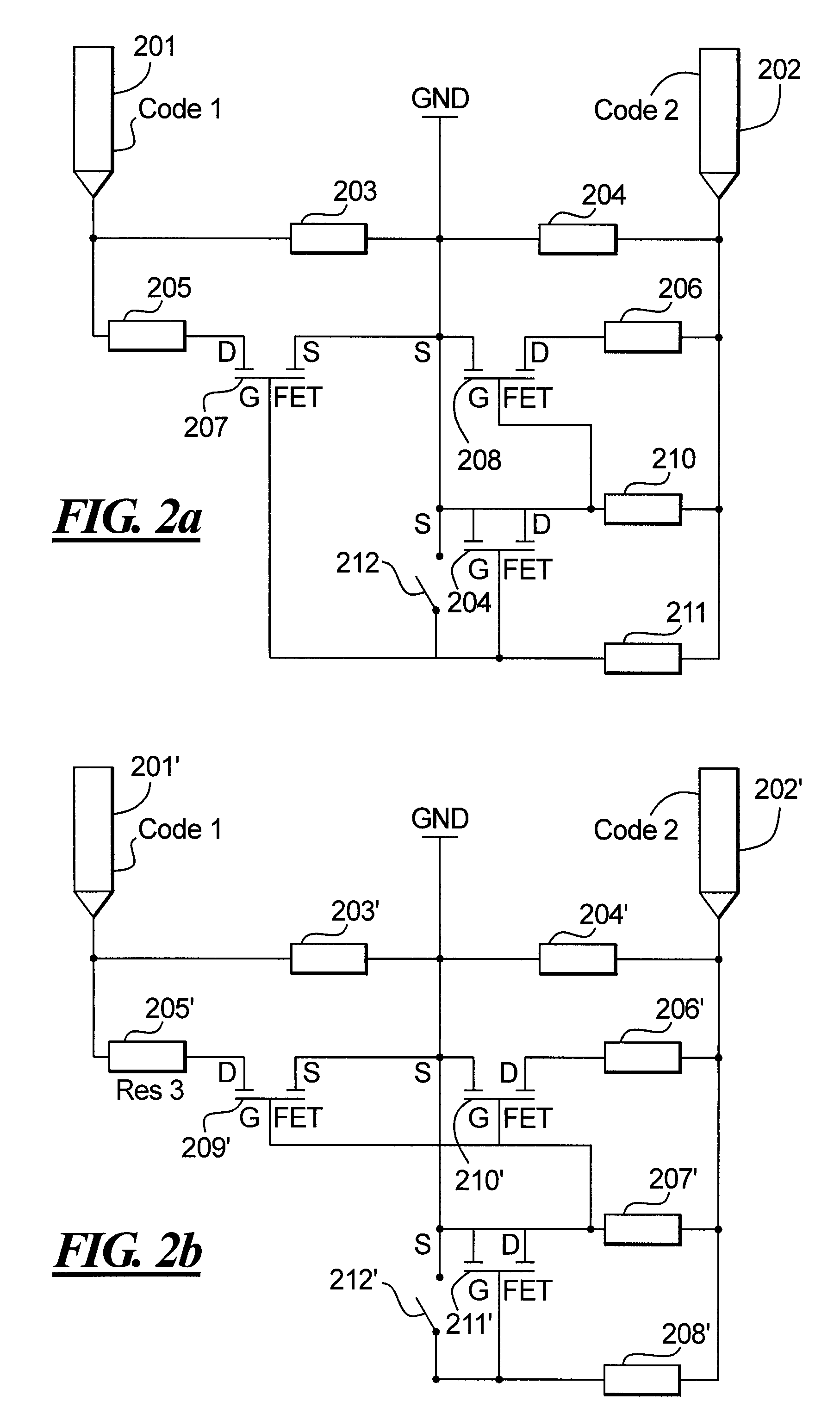
[0035]In the first embodiment, an internal resistance circuit in the main coil is used as a basis, the resistance circuit comprises a sub-coil switch which is closed after the sub-coil is plugged in and a transistor that controls the jump of the resistance value; the transistor can be a field effect transistor or a triode. When the sub-coil is plugged into a corresponding socket of the main coil via its coil plug, the sub-coil switch in the internal resistance circuit of the main coil is closed. The closing of the switch leads to a short circuit in a part of the resistance circuit, which controls the change of the transistor's state, further leading to the jump of the total resistance value of the resistance circuit, thus realizing the change in the combined receiving coil voltage value assigned by the system after the sub-coil is connected to the main coil, for example the assigned voltage becomes bigger or smaller, namely, a desired change is realized in which the identification c...

second embodiment

[0063]FIG. 4 is a diagram of a first particular example of the second embodiment according to an identification code circuit provided by the present invention, and as shown in the figure, the number of the identification code is one; the number of the sub-coils is two. Since the object of FIG. 4 is merely to show the fundamental principles of the embodiment, each part in the figure does not represent actual components in an actual circuit, it just represents the schematic framework of each part in the circuit. A fifteenth fixed resistor 401 represents the corresponding fixed resistor of the main coil, of which the value is 1920Ω; an eleventh regulating resistor 402 represents the corresponding regulating resistor of the first sub-coil which is connected to the main coil, of which the value is 1430Ω; a twelfth regulating resistor 403 represents the corresponding regulating resistor of the second sub-coil which is connected to the main coil, of which the value is 875Ω; an eighth sub-c...


PUM


Abstract

An identification code circuit for a receiving coil in a magnetic resonance imaging system, is embodied in a main coil. The circuit has a fixed resistance for generating the identification code of the main coil. The main coil has a socket for connecting a sub-coil, so that a coil plug of a sub-coil can be plugged into the socket for connecting to the main coil. The identification code circuit also has a regulating resistance and a sub-coil switch corresponding to the socket. The coil plug of the sub-coil is plugged into the socket to close the sub-coil switch, so that the values of the regulating resistance and said fixed resistance are added together to form a combined resistance value. After said main coil has been connected to a magnetic resonance imaging system, an identification code source voltage value across the combined resistance value is the identification code of the combined main coil and sub-coil. A receiving circuit identification code thus can be generated simply and with reduced cost.

Description

BACKGROUND OF THE INVENTION[0001]1. Field of the Invention[0002]The present invention relates to the magnetic resonance imaging (MRI) technology and, in particularly to an identification code circuit for a receiving coil in a magnetic resonance imaging system.[0003]2. Description of the Prior Art[0004]Magnetic resonance imaging is an imaging technology utilizing the magnetic resonance phenomenon. The basis of magnetic resonance phenomenon is that, for an atomic nucleus with an odd number of protons, such as the atomic nucleus of hydrogen which widely exists in the human body, the protons thereof have spin moments, just like a tiny magnet, and the spin axis of these tiny magnets normally has no regularity. If an external magnetic field is applied, however, the spin axis of these tiny magnets will be realigned by the magnetic field lines of the external magnetic field. In this state, by emitting radio frequency (RF) pulses with a specific frequency in order to excite the nuclei, these...

Claims


Application Information

Patent Timeline
Patent Type & Authority Patents(United States)
IPC IPC(8): G01V3/00
CPCG01R33/36G01R33/288
Inventor WANG, JIAN MINZHU, HUA BIN
Owner SIEMENS HEALTHCARE GMBH
Why Eureka
Try Eureka